Process Summary
Fluid Catalytic Cracking (FCC) consists in cracking of various types of hydrocarbon feedstock in the presence of a catalyst (as clay) in various forms (as pellets or beads, either stationary in a fixed bed or moving through the oil or as a fine powder fluidized by a stream of air or hydrocarbon vapors), distinguished from thermal cracking, and in the absence of hydrogen as opposed to hydrocracking.
In its most common application, FCC is converting heavy hydrocarbon feedstock such as straight run atmospheric gas oil, vacuum gas oils, atmospheric residues, and heavy stocks recovered from other operations, into high octane gasoline, light fuel oils and olefin-rich light gases. FCC is also applied to cracking lighter feedstock such as light straight run or paraffinic naphtha as availability is increasing.
Depending upon the catalyst characteristics and the operational conditions with cracking temperatures higher than 500°C, the FCC process is inefficient to cracking aromatic compounds, therefore, the higher the paraffinic content in the feedstream, the higher the conversion rate.
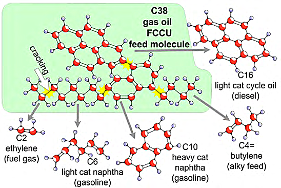
Fig. 1 illustrates the results of hydrocarbon cracking in a Fluid Catalytic Cracking Unit (FCCU). The FCCU cracks multiple bonds within gas oil molecules containing many carbon atoms and thereby produces a variety of smaller molecules containing fewer carbon atoms. One of these smaller molecules in the example shown is a 10-carbon molecule that belongs to the heavy cat naphtha intermediate product group; after undergoing additional refining processes, it becomes a high-octane gasoline blending component.
Figure 1 - Molecules from C38 Gasoil cracking in a FCCU[2].
Process Units
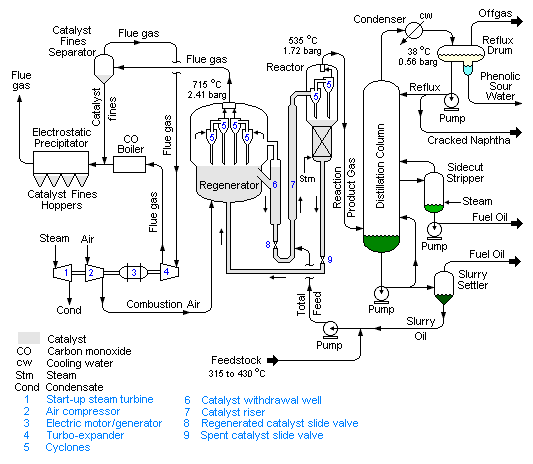
The FCC process is best visualized as cyclic process, the key components of the FCCU are the reactor, the regenerator and the fractionator (Fig. 2).
Figure 2 - FCC simplified Process Flow Diagram[3].
.jpeg)
- Reactor
Feed is heated and mixed with the catalyst; reaction starts even before the fluid reaches the reactor; therefore, the residence time in the reactor vessel is very short. The prime role of the reactor is to function as a catalyst separator removing spent (coked) catalyst and direct it to the regenerator with cracked products moving on to the fractionator.
- Regenerator
Rather than introduce expensive fresh catalyst to the process, the existing coke covered spent catalyst coming from the reactor can be regenerated by removing the coke deposits using high temperature air at around 600 - 700°C. Coke burning proceeds through oxidation with oxygen into CO.
- CO Boiler
The carbon monoxide is burned in a boiler capable of generating higher pressure steam that supplies other process units in the refinery.
- Fractionator
The fractionating column separates the light ends, gasoline, and fuel oils. The remaining bottoms product is termed cycle oil and is typically fed back to the beginning of the process where it is mixed with the fresh feed.
Operating Conditions and Cracking Yields
Usually, catalytic cracking units are geared towards the production of fuels (mainly gasoline) and have been developed to crack heavier feedstock. However, some process units are optimized to maximize the production of light olefins (propylene and ethylene) via increased cracking severity translating into higher operation temperature reaching 600°C or higher, a higher catalyst-to-oil ratio and the use of catalyst modifiers such as ZSM-5 zeolite.
Typical, comparative cracking yields are shown in Table 1.
Table 1 - Typical Cracking Yield by Process Type[4]
| Weight-% |
Ethylene |
Propylene |
Butylenes |
Gasoline |
| FCC |
1-2 |
3-5 |
6-8 |
45-55 |
| R2P* |
1-2 |
10-12 |
12-14 |
28-35 |
| DCC* |
2-6 |
15-25 |
13-17 |
22-40 |
| HS-FCC* |
3-4 |
16-20 |
13-16 |
30-40 |
| C2 SC* |
45-50 |
1-3 |
1-2 |
1-3 |
| NCC* |
7.1 |
16.8 |
8.6 |
48.5 |
*R2P: Resid-to-Propylene, DCC: Deep Catalytic Cracking, HS-FCC: High Severity FCC, C2 SC: Ethane Steam Cracking, NCC: Naphtha Catalytic Cracking.
Fig. 3 presents the results of a comparative study carried out by Technip, showing the yields obtained by conventional FCC units, FCC units optimized for the production of olefins (FCC to olefins), and HS-FCC™ designed to maximize the production of petrochemical intermediates.
Figure 3 - Comparative Study between Conventional FCC and Petrochemical FCC (HS-FCC™)[5]
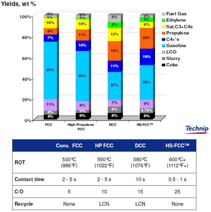
It shows that a higher reaction temperature and a catalyst-to-oil ratio three to five times higher when compared with conventional process units has the result of the yield of light olefins (Ethylene + Propylene + C4 olefins) increasing from 14 % to 36% and 40%.
References
- Merriam Webster, Catalytic Cracking.
- Warren Averill, 2024, Full Conversion Petroleum Refinery Handbook for Operators, Chapter 1, Refinery Overview, Provided by Visual Performance Solutions, Inc.
- SULZER, Fluid catalytic cracker (FCC)
- Christopher Dean, May 2015, Naphtha Catalytic Cracking in FCC Units Past & Present, REFCOMM GALVESTON May 4-8 2015.
- M. W. da Silva, 3rd Jan 2023, The Role of Fluid Catalytic Cracking Technologies in the Future of Downstream Industry.







.jpeg)


