Technology Overview
K-COT™ (KBR Catalytic Olefins Technology) is a fluidized catalytic cracking process that converts low-value C4–C10 olefinic, paraffinic, or mixed hydrocarbon streams into high-value propylene, ethylene, and aromatics-rich (BTX) gasoline. It couples a proprietary modified ZSM-5 catalyst with KBR’s Orthoflow™ fast-fluidized FCC reactor system, drawing on more than 70 years of KBR fluid-bed reactor design experience and over 100 KBR-designed olefins recovery plants.
K-COT can serve as an alternative to steam cracking for paraffinic feeds such as straight-run naphtha, or as an adjunct “recycle converter” that upgrades low-value steam cracker and refinery by-products (mixed C4s, C5s, cracked naphthas, aromatics raffinate) as well as non-traditional streams (methanol, ethanol, and Fischer-Tropsch or MTO/MTP by-products) — all without feed pretreatment. Compared with steam cracking, it operates at significantly lower temperatures (~600–700 °C vs. >850 °C), delivers a much higher propylene-to-ethylene ratio (~1:1 on paraffinic feeds, up to ~2–2.5:1 on olefin-rich feeds), 10–25% relatively higher light olefin yields, roughly 50% more BTX, and lower cost of production, capital cost, and CO2 emissions.
Process History
| Year |
Milestone |
| 1942 |
KBR predecessor (M.W. Kellogg) constructs the world's first commercial FCC unit (ExxonMobil Baton Rouge) — origin of the Orthoflow™ converter lineage |
| 1961 |
KBR licenses the world's first residue FCC (Phillips Borger) |
| Following decades |
Continuous FCC innovation: Orthoflow F with riser cyclones, Atomax™ feed nozzles, MAXOFIN™, RegenMax™, stripper packing, CycloFines™ TSS, self-aerated spent catalyst distributor; 120+ grassroots FCC licenses and 270+ revamps |
| 2006 |
First commercial catalytic olefins unit on olefinic feed (SUPERFLEX™ heritage, now counted as the first K-COT commercial application) started up at Sasol, Secunda, South Africa (~250 KTA propylene) |
| 2008–2010 |
ACO process co-developed by SK (catalyst from SK R&D, Daejeon) and KBR (Orthoflow hardware, pilot-plant verification, worldwide licensing rights) |
| Oct 2010 |
Start-up of the ACO Commercial Demonstration Unit at SK Energy's Ulsan complex, South Korea (67 KTA naphtha feed; 40 KTA ultimate olefins); 6-month parametric demonstration program on light, full-range, and FCC cracked naphthas |
| 2011–2017 |
ACO technology rebranded/consolidated as K-COT™, combining KBR's catalytic olefins know-how for all feed types into one offering |
| Late 2010s |
Commercial K-COT unit at Lotte Chemical Titan, Pasir Gudang, Malaysia |
| 2020s |
Additional licenses worldwide; stand-alone small-scale projects under development in China; K-COT positioned as a key crude-to-chemicals and energy-transition technology with a defined path to net zero |
Process Summary and Chemistry
Summary
A preheated, vaporized hydrocarbon feed (mixed with dilution steam) is contacted with hot regenerated modified-ZSM-5 catalyst in a short-contact-time riser reactor at ~600–700 °C. Cracking is endothermic; heat is supplied by the circulating catalyst. Because light feeds deposit very little coke, supplemental fuel is fired continuously into a patented catalyst well in the regenerator to maintain heat balance. Catalyst is separated from the reactor effluent in a disengager with high-efficiency cyclones, stripped, and regenerated with air. Reactor effluent passes through a patented oil-wash catalyst-fines removal system and water quench, then through a conventional olefins-plant recovery section (depropanizer-first flow scheme) with additional trace-impurity removal specific to FCC-type effluents. C4–C6 non-aromatics are recycled to extinction without hydrotreating.
Chemistry
Catalytic cracking over the acidic, medium-pore ZSM-5 zeolite proceeds via carbenium-ion chemistry rather than the free-radical chemistry of steam cracking:
-
Initiation (paraffinic feeds): protolytic (monomolecular) cracking of paraffins at Brønsted acid sites — C–C bond protonation and cleavage to a smaller paraffin plus olefin, with minor dehydrogenation to H2 and olefins. Requires high temperatures, hence riser outlet temperatures well above conventional FCC.
-
Propagation: olefins protonate rapidly to carbenium ions; beta-scission of carbenium ions produces propylene and butylenes (and some ethylene) preferentially. Olefins crack orders of magnitude faster than paraffins, which is why olefinic feeds achieve higher conversion and higher propylene-to-ethylene ratios.
-
Oligomerization–cracking cycles: light olefins oligomerize and re-crack, with equilibria favoring C3–C4 olefins at operating severity.
-
Aromatization: olefin cyclization followed by hydrogen transfer/dehydrogenation yields BTX aromatics; ZSM-5 shape selectivity favors mononuclear aromatics, giving an aromatics-rich (>50% aromatics) gasoline by-product.
-
Hydrogen transfer suppression: relative to Y-zeolite FCC catalysts, ZSM-5 suppresses bimolecular hydrogen transfer, preserving product olefinicity and minimizing coke make (very low versus refinery FCC), with some olefin saturation to LPG-range paraffins.
-
Undesired reactions: thermal (radical) cracking at riser temperatures generates dry gas (methane, ethane); minor coke deposition.
-
Oxygenates: methanol and ethanol dehydrate over the acid sites to light olefins (via DME/hydrocarbon-pool-type pathways), then enter the same cracking/aromatization network — enabling direct processing of oxygenate-containing feeds.
-
Dilution steam lowers hydrocarbon partial pressure, favoring monomolecular cracking, improving olefin selectivity, and reducing coke formation.
Detailed Process Description (Reaction → Quench → Recovery)
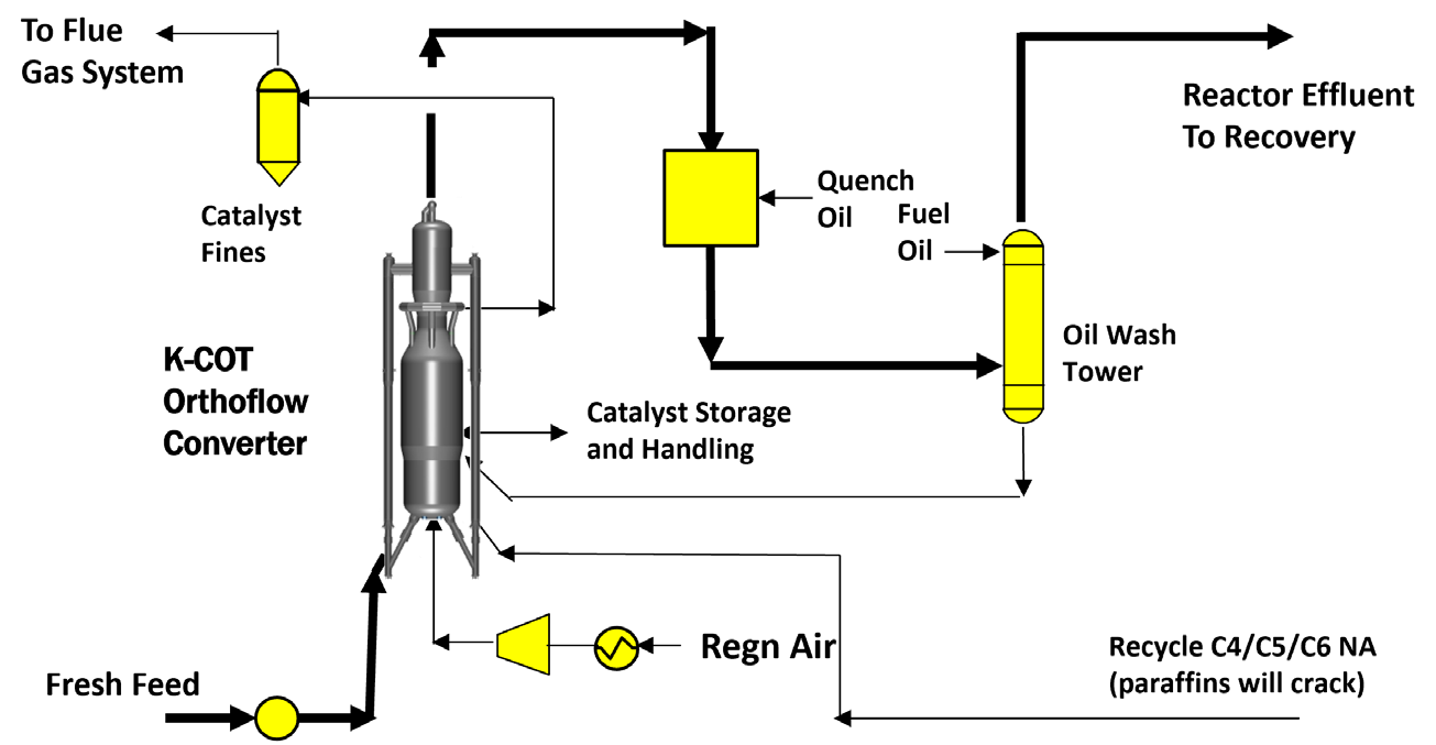
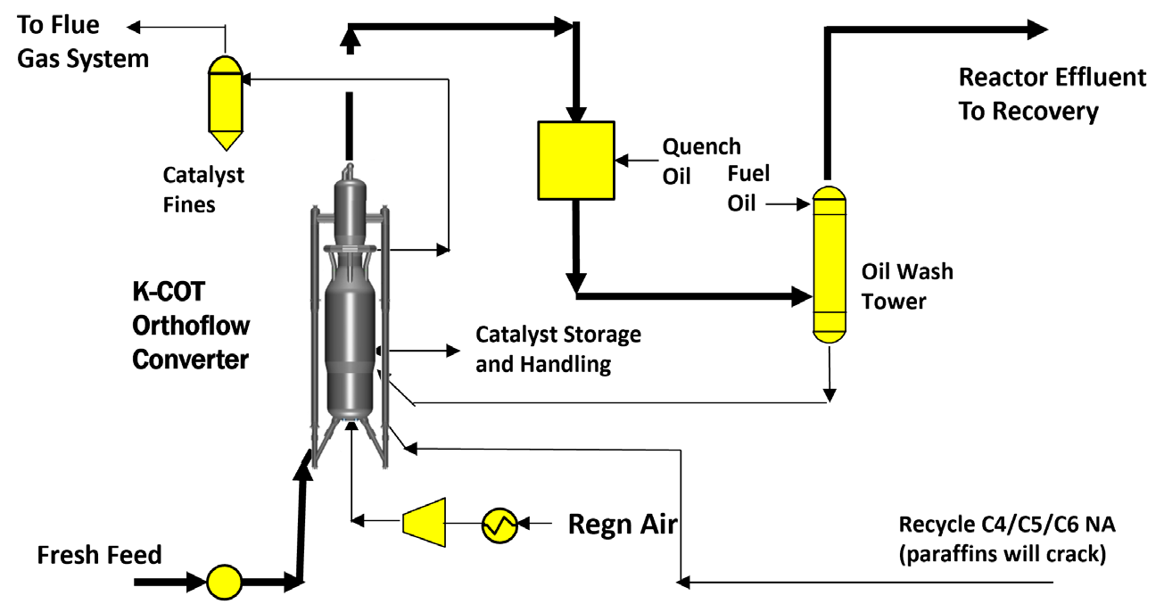
Figure 1 - K-COT™ Process Flow Diagram
1. Feed and preheat: Fresh liquid feed is pumped, preheated by feed/effluent heat exchange, vaporized, combined with dilution steam (steam/hydrocarbon ≈ 0.30 wt), and superheated (demo unit: 482 °C). Olefinic recycle streams (C4/C5/C6 non-aromatics) join without any hydrotreating or pretreatment.
2. Riser reactor: The feed/steam mixture is injected through multiple open-pipe injection nozzles (four in the demo unit) at the base of the riser, where it contacts hot regenerated catalyst. Cracking occurs in the vapor phase with a catalyst/vapor contact time of ~2 seconds and a riser outlet temperature of ~675 °C. Catalyst circulation (demo unit: 4.3 t/min; catalyst/feed ratio ≈ 32) is set by the regenerated-catalyst slide valve, which controls riser temperature. A single reactor train can serve capacities from ~200 KTA up to 1,200 KTA of combined ethylene plus propylene.
3. Disengager: A closed-cyclone riser termination device effects rapid catalyst/vapor separation to prevent over-cracking of desired products; two-stage cyclones achieve ~99.9975% separation efficiency. Vapors flow to quench; catalyst flows to the stripper. Disengager pressure floats on the downstream system (demo: 1.75 kg/cm2g).
4. Spent catalyst stripper: Two-stage steam stripping with traditional baffles: an upper steam distributor displaces entrained hydrocarbons, a lower distributor reduces partial pressure to diffuse hydrocarbons out of catalyst pores. Medium-pressure steam; stripped catalyst flows via standpipe/plug valve (stripper level control) to the regenerator.
5. Regenerator and patented catalyst well (heat balance): Coke is burned off with air, but coke make from light feeds is far too low to balance the endothermic cracking duty. External fuel (fuel oil and/or fuel gas — by-product fuel oil can be used) is fired continuously in KBR’s patented, commercially proven catalyst well; the regenerator effectively functions as a “catalyst heater.” Conditions (demo): bed 730 °C, dilute phase 750 °C, excess O2 3 vol% (dry), pressure 2.10 kg/cm2g; single-stage cyclones (~99.98% efficiency); flue gas routed to a CO boiler/flue-gas system for heat recovery.
6. Regenerated catalyst stripper (unique feature): A rigid packed zone with medium-pressure steam strips entrained combustion gases (N2, O2, COx, NOx) from the regenerated catalyst — preventing contamination of the cracked gas — and fluidizes the catalyst for smooth standpipe flow back to the riser.
7. Catalyst management: Modified ZSM-5 proprietary catalyst; average particle size ~80 µm, fines (<45 µm) <8%. Demo-unit inventory 22 t; fresh catalyst make-up ~1% of inventory per day via catalyst storage and handling hoppers.
8. Oil wash tower — patented catalyst fines removal and quench oil system: Reactor effluent is quenched in the oil wash tower; KBR’s patented solids-removal design captures carried-over catalyst fines in circulating wash oil and recycles backflush oil with fines to the reaction system, delivering solids-free light products overhead. The unique quench oil column includes the catalyst recycle scheme; heat is recovered as steam; a distillate stripper separates heavy gasoline and fuel oil. This is followed by a water quench tower with process-water/dilution-steam generation closing the steam loop.
9. Compression, treating, and cold recovery (depropanizer-first scheme): Quenched gas is compressed (cracked gas compressor), caustic-scrubbed for acid gas, and dried. Proprietary trace-impurity removal addresses FCC-effluent-specific contaminants — oxygen, nitrogen oxides, acetylene (acetylene converter / O₂ reactor option), and oxygenates. The cold section comprises cold box/demethanizer (C2 refrigeration), deethanizer, C2 and C3 splitters (C3 refrigeration), and PSA for hydrogen recovery, producing polymer-grade ethylene and propylene. A dehexanizer separates the BTX-rich C6+ gasoline (optional gasoline hydrotreating for aromatics extraction) from the C4–C6 non-aromatics, which are recycled to the reactor to extinction via a simplified recycle circuit. Ethane/propane are recycled (to the K-COT reactor or to cracker furnaces in integrated configurations). KBR cites lower capital investment, high on-stream factor, wide turndown flexibility, smooth start-ups, and low maintenance for this recovery design.
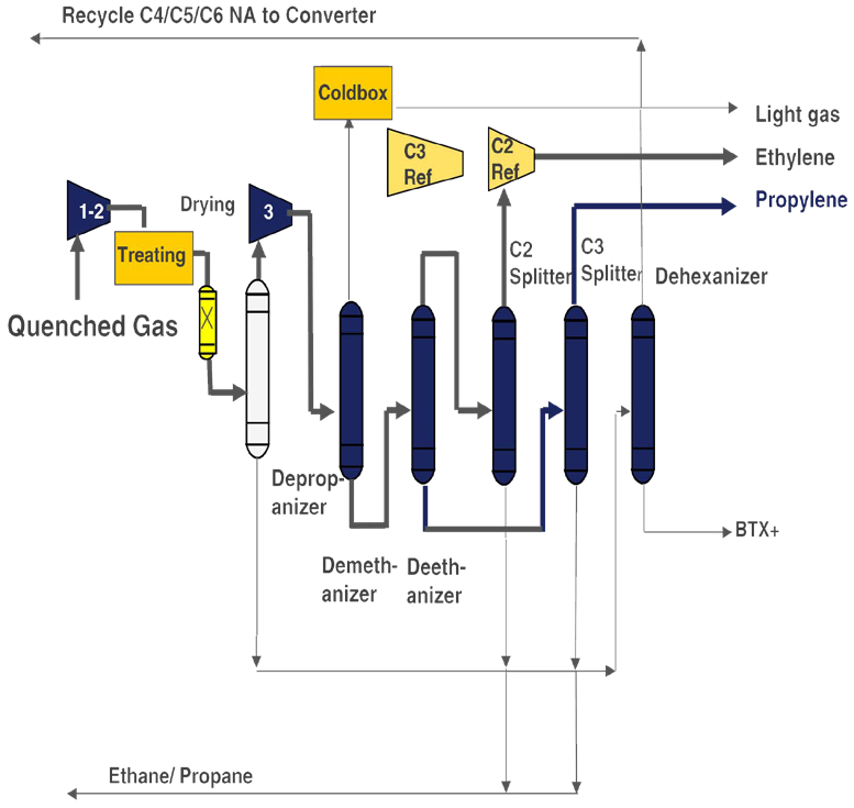
Figure 2 - Typical K-COT™ recovery flow scheme
Key demonstration-unit operating parameters (SK Ulsan, LSR naphtha feed):
| Parameter |
Value |
| Fresh feed |
8,000 kg/h (64–67 KTA LSR naphtha: ~46% n-paraffins, ~46% iso-paraffins, ~6.6% naphthenes, ~1.6% aromatics) |
| Feed preheat (with dilution steam) |
482 °C |
| Dilution steam ratio |
0.30 wt steam/HC |
| Riser outlet temperature |
675 °C |
| Catalyst/vapor contact time |
~2 s |
| Catalyst circulation |
4.3 t/min (cat/feed ≈ 32) |
| Disengager / regenerator pressure |
1.75 / 2.10 kg/cm2g |
| Regenerator bed / dilute phase |
730 / 750 °C |
| Excess O₂ in flue gas |
3 vol% (dry) |
| Ultimate olefins (C2= + C2=) |
~40 KTA |
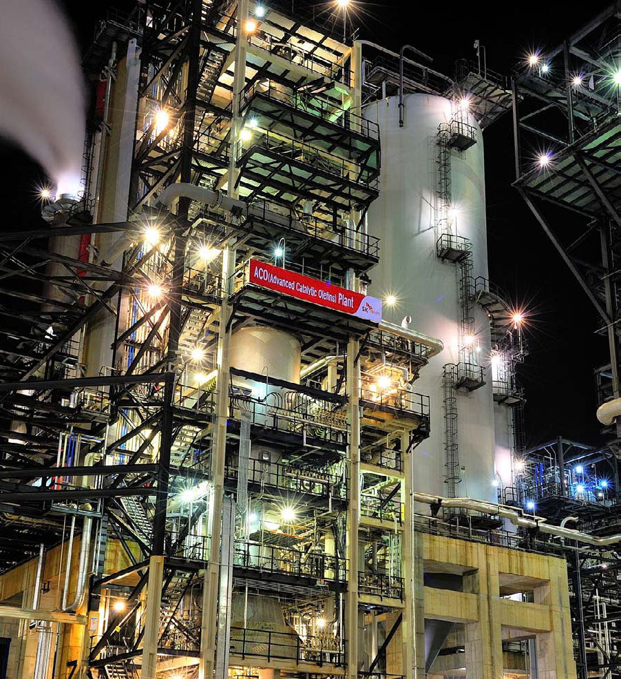
Figure 3 - K-COT™ Plant at SK in Ulsan
10. Integration configurations:
-
Stand-alone olefins plant (grassroots, incl. small-scale; only ethylene/propylene derivatives plus aromatics or high-octane gasoline as products).
-
Recycle converter integrated with a liquid steam cracker: C4/C5/C6 NA by-products upgraded without hydrotreating; replaces furnace expansions or old high-maintenance furnaces.
-
Integration with gas crackers (e.g., ethane crackers) to add propylene capacity and feed flexibility.
-
Refinery integration for surplus straight-run or cracked naphtha (FCC, coker, visbreaker), improving gross refinery margin.
-
KBR Combined Olefins Process: SCORE™ steam cracking + K-COT sharing one recovery train for maximum feed and product flexibility.
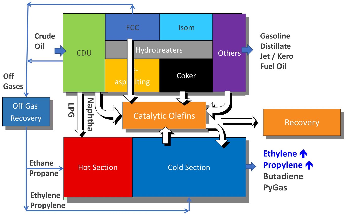
Figure 4 - K-COT™ optimized integration scheme.jpeg
Feedstock Flexibility
| Feed |
K-COT |
SCORE (steam cracking) |
| Ethane / propane |
— |
✓ |
| Butane |
✓ |
✓ |
| Straight-run naphtha |
✓ |
✓ |
| Steam cracker olefinic C4s/C5s |
✓ (untreated) |
✓ (hydrogenated) |
| Aromatics raffinate (C6–C8 NA) |
✓ |
— |
| Refinery mixed C4s |
✓ |
— |
| FCC / coker / visbreaker naphtha |
✓ |
— |
| Methanol, ethanol, other oxygenates |
✓ |
— |
| FT / MTO / MTP by-products |
✓ |
— |
K-COT: P/E ratio up to ~2.5 and olefins yield up to ~60 wt% (feed-dependent).
Process Performance
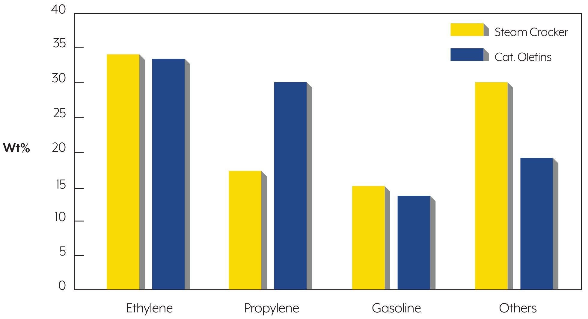
Figure 5 - Typical yields comparison for different naphtha cracking technologies
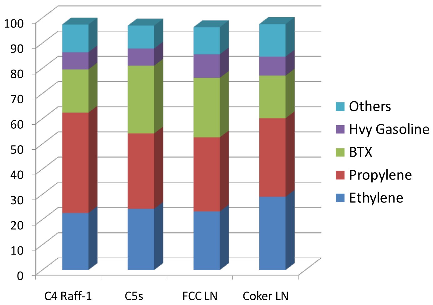
Figure 6 - Typical K-COT™ ultimate yields from olefinic feed.jpeg
-
Demo unit vs. pilot plant (LSR naphtha): total ethylene + propylene essentially equal; demo showed slightly more propylene and slightly less ethylene; methane and diolefins marginally high in early runs, with optimization via riser temperature, dilution steam ratio, and cat/oil ratio.
Case study — 2,004.5 KTA light straight-run naphtha (ultimate material balance, KTA):
| Stream |
Steam cracker |
ACO / K-COT |
| Ethylene |
700.0 |
697.2 |
| Propylene |
347.9 |
613.2 |
| Tail gas |
359.5 |
357.3 |
| Butadiene |
101.1 |
0 |
| C4 raffinate |
126.4 |
0 |
| Gasoline (BTX-rich) |
339.2 |
298.2 |
| Acid gas |
1.2 |
3.6 |
| Fuel oil + coke |
29.2 |
35.0 |
Combined
C2= + C3= |
1,047.9
(~52 wt%) |
1,310.4
(~65 wt%) |
No butadiene extraction or C4/C5 treating required — all C4/C5 streams are consumed in the process.
Economic Performance
-
Case study (above, 2010-era price deck): operating margin improved by ~$52 MM/yr; cost of production $1,007 vs. $1,080/MT ethylene (≈$67/MT ethylene, ≈$186/MT olefins lower); ~10% lower specific energy (kcal/kg olefins); slightly lower total installed cost; simple payout 3.9 vs. 4.7 years.
-
Current KBR positioning: production cost up to ~$70/t ethylene below thermal cracking, with lower total installed cost.
-
Integration with a liquid cracker: average margin uplift ~$58/t ethylene over the period studied; simple payout <3 years.
-
Integration with a 1,800 KTA ethane cracker (USGC basis, relative indices):
| Configuration |
ISBL TIC |
Ethylene |
C2= + C3= |
TIC per t
C2= + C3= |
Standalone
ethane cracker |
100 |
100 |
100 |
100 |
Integrated K-COT
+ C2 cracker |
103 |
84 |
119 |
87 |
Integrated K-COT + C2
cracker + C4 processing |
118 |
81 |
131 |
91 |
-
Scale economics: single-reactor capacities from 200 to 1,200 KTA olefins; economic even at small scale (PE and PP economy of size; simplified recovery), with small-scale projects under development in China.
Commercial Experience and Deployments
| Site |
Start-up |
Scope |
| Sasol, Secunda, South Africa |
2006 |
First commercial catalytic olefins unit on olefinic feed (SUPERFLEX heritage); ~250 KTA propylene; recovery section designed for additional olefin-rich streams up to 525 KTA propylene + 200 KTA ethylene |
| SK Energy / SK Innovation, Ulsan, South Korea |
Oct 2010 |
ACO commercial demonstration unit: 67 KTA naphtha feed, 40 KTA ultimate olefins; achieved design feed rate on schedule; validated performance across light, full-range, and FCC cracked naphthas in a 6-month parametric program |
| Lotte Chemical Titan, Pasir Gudang, Malaysia |
late 2010s |
Commercial K-COT unit |
| Several additional licenses worldwide, including projects in China |
ongoing |
Per KBR |
Sustainability — Path to Net Zero
K-COT is positioned as an energy-transition technology (upgrading surplus gasoline-range streams to chemicals; crude-to-chemicals). Decarbonization levers identified by KBR: electric motor drives for all compressors (commercial experience in K-COT); electrification of the regenerator (CFD proof-of-concept completed, commercial demonstration sought); maximizing air preheat; shifting regenerator fuel from fuel oil to H2-rich fuel gas or imported hydrogen; single-point CO2 capture (only one flue-gas source, simplifying CCUS); and sustainable feeds (ethanol/methanol, bio-oil, plastics pyrolysis oil).
References
A. Primary KBR technical documents
- KBR — Catalytic Olefins Technologies Provide Refinery/Petrochemical Balance (Oct 2010). Presented at the 25th JPI Petroleum Refining Conference “Recent Progress in Petroleum Process Technology”, Tokyo, Japan
- KBR — Tallman M.J.: Sustainable Catalytic Cracking Technology Useful for the Energy Transition, TNChE 2024, Pattaya, Thailand (Jun 19, 2024)
- KBR — Singh R.: Maximizing Refinery Margins by Petrochemical Integration, GRPC (May 2017)
- KBR — Technology Flyer K19031: Improve Propylene Yields From Straight Run Naphtha Cracking with KBR Catalytic Olefins Technology (K-COT™) (Mar 2022)
- KBR — Brochure K19032: KBR Catalytic Olefins Technology – K-COT™: Feed-flexible technology to maximize propylene yield (Oct 2022)
B. KBR corporate resources
- KBR — KBR Official Website — Solutions / Process Technologies (accessed: Aug 2026)
- KBR — KBR Newsroom — Press Releases (accessed: Aug 2026)
C. Communications
- Semantic Scholar — A CATALYTIC CRACKING PROCESS FOR ETHYLENE AND PROPYLENE FROM PARAFFIN STREAMS THE ADVANCED CATALYTIC OLEFINS ( ACO ) PROCESS (2007)
- Chemical Online — KBR And SK Corporation To Commercialize And Market New Catalytic Process For Olefins Production From Paraffinic Feeds (Jul 30, 2007)
- Industrial Info — SK Energy's First Advanced Catalytic Olefins Technology-Based Naphtha Cracker to Begin in October (May 27, 2010)
- Researchgate — Asia-Pacific: KBR and SK Innovation have started up their advanced catalytic olefins (ACO) demo plant in Ulsan, South Korea (Mar 1, 2011)
- AIChE — Advanced Catalytic Olefins (ACO) : First Commercial Demonstration Unit Begins Operations (Mar 14, 2011)
- Researchgate — Asia-Pacific: KBR and SK Innovation have started up their advanced catalytic olefins (ACO) demo plant in Ulsan, South Korea (Mar 1, 2011)
- Hydrocarbon Processing — KBR, SK Group license advanced catalytic olefins technology to China plant (Oct 17, 2011)
- DigitalRefining — KBR Announces first license for the advanced catalytic olefins (ACO™) process (Oct 17, 2011)
- KBR — KBR Awarded Catalytic Olefins Technology Contract (Dec 2, 2014)
- oil&gas Portal — New Catalytic Process for Production of Olefins (Apr 17, 2015)
- The Edge Malaysia - Lotte Chemical gets DOE stop-work order to fix odour emission (Oct 2, 2017)
- KBR — Leading Midstream Company Selects KBR’s Catalytic Olefins Technology for US Petrochemicals Project | KBR (Mar 24, 2022)
- Chemical Engineering — KBR launches integrated technology suite for decarbonizing catalytic olefins processes - Chemical Engineering (Jul 09, 2024)
D. Patents
- Inventor: Robert B. Peterson, Chris Santner, Michael Tallman. United States patent US7153479B2: Catalyst regenerator with a centerwell. Oct 10, 2002: Application filed by Kellogg Brown and Root LLC
- Inventor: Michael Tallman, Robert B. Peterson, Maureen F. Gilbert. Catalyst recovery from light olefin FCC effluent. Oxt 10, 2002: Application filed by Kellogg Brown and Root LLC
- Inventor: Alain Claude. World patent WO2009145868A1: Fcc for light feed upgrading. Dec 5, 2009: Application filed by Kellogg Brown and Root LLC
- Inventor: Alain Claude, Anand Subramanian. World patent WO2009145869A1: Heat balanced fcc for light hydrocarbon feeds. Dec 5, 2009: Application filed by Kellogg Brown and Root LLC