Process Summary
The Chlor-Alkali electrolysis process is used in the manufacture of chlorine, hydrogen, and sodium hydroxide (caustic) solution. Of these 3, the primary product is chlorine. There are 3 types of electrolytic processes used in the production of chlorine:
- the Diaphragm Cell Process,
- the Mercury Cell Process, and
- the Membrane Cell Process.
In each process, a salt solution is electrolyzed by the action of direct electric current that converts chloride ions to elemental chlorine. The overall process reaction is[1]:
2 NaCl + 2 H2O → Cl2 + H2 + 2 NaOH
Most of the time, sodium chloride is used in the process and less frequently potassium chloride is used. Due to the much higher raw material costs, potassium chloride is only used when the desired product is potassium hydroxide[2].
In all 3 methods, the chlorine (Cl2) is produced at the positive electrode (anode) and the caustic soda (NaOH) and hydrogen (H2) are produced, directly or indirectly, at the negative electrode (cathode). The three processes differ in the method by which the anode products are kept separate from the cathode products[1].
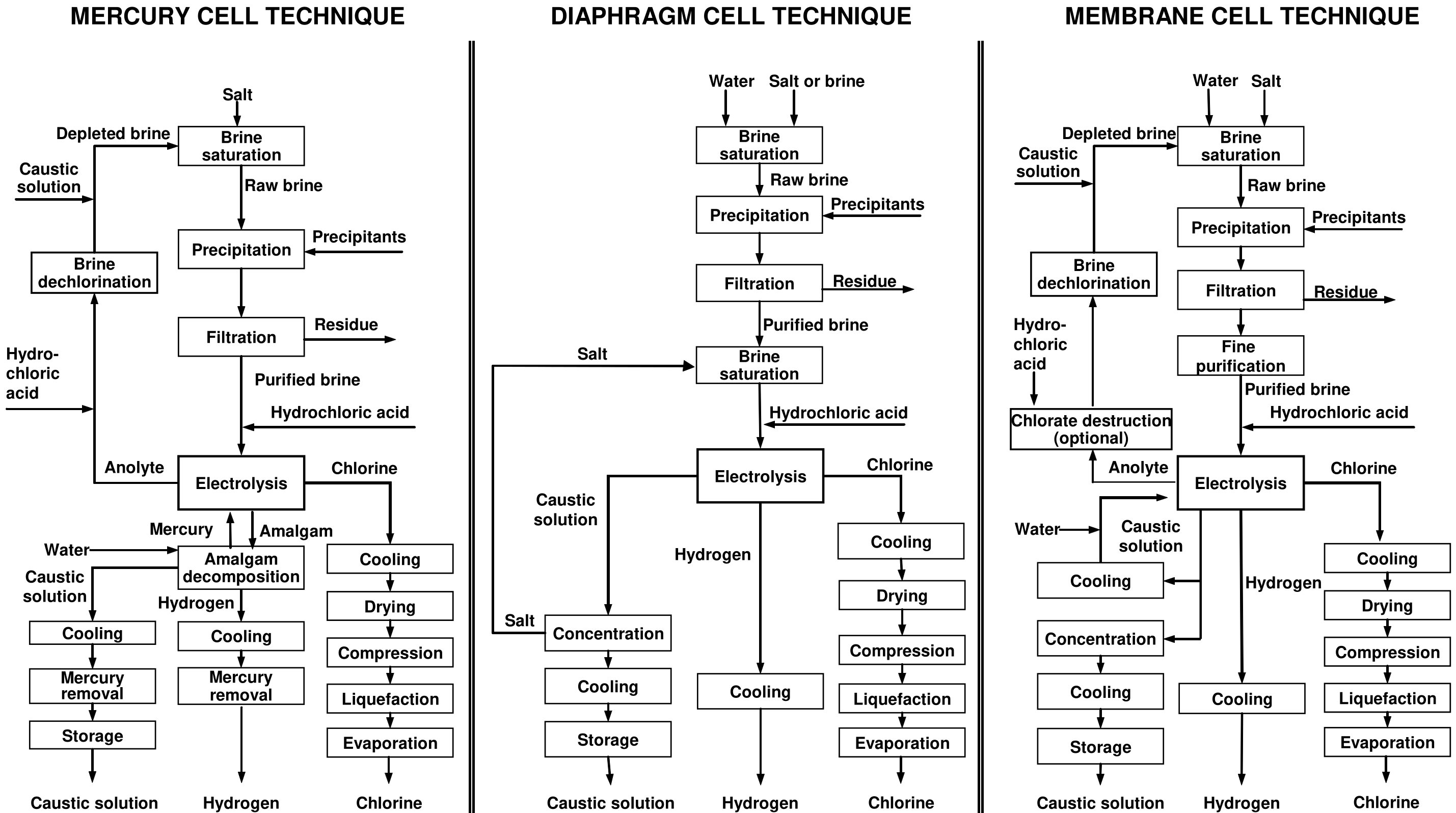
An industrial chlor-alkali production unit comprises a series of operations, typically structured as shown in the illustration image[2].
Main characteristics of the three cell processes are shown in Table 1.
Table 1 - Main typical characteristics of the different electrolysis techniques[2].
| Criterion |
Mercury |
Diaphragm |
Membrane |
| Anode |
RuO2 + TiO2 coating on
Ti substrate |
RuO2 + TiO2 +
SnO2 coating
on Ti substrate |
RuO2 + IrO2 + TiO2 coating
on Ti substrate |
| Cathode |
Mercury |
Steel (or steel
coated with
activated nickel) |
Nickel coated
with high area
nickel-based or
noble metal
-based coatings |
| Separator |
None |
Asbestos,
polymer-modified
asbestos, or
non-asbestos
diaphragm |
Ion-exchange
membrane
|
| Cell voltage |
3.15–4.80V |
2.90–3.60V |
2.35–4.00V |
| Current density |
2.2–14.5kA/m2 |
0.8–2.7kA/m2 |
1.0–6.5kA/m2 |
| Temperature |
Inlet: 50–75°C
Outlet: 80–90°C |
n.a. |
n.a. |
| pH |
2-5 |
2.5-3.5 |
2-4 |
| Cathode product |
Sodium amalgam
(Na-Hgx) |
10–12wt-% NaOH and H2 |
30–33wt-% NaOH and H2 |
| Decomposer product |
50wt-% NaOH and H2 |
No decomposer needed |
No decomposer
needed
|
| Evaporator product |
No evaporation
needed |
50wt-% NaOH |
50wt-% NaOH |
Quality of
caustic soda
(50 wt-% NaOH) |
NaCl: ~50mg/kg
NaClO3: ~5mg/kg
Hg: ~0.1mg/kg |
NaCl: ~10,000mg/kg
(15,00017,000
mg/kg before concentration)
NaClO3: ~1 000mg/kg
(400 –500mg/kg before
concentration)
O2: 0.5–2.0vol-% |
NaCl: ~50mg/kg
NaClO3: ≤10–50mg/kg |
| Chlorine quality |
O2: 0.1–0.3vol-%
H2: 0.1–0.5vol-%
N2: 0.2–0.5vol-% |
O2: 0.5–2.0vol-%
H2: 0.1–0.5vol-%
N2: 1.0–3.0vol-% |
O2: 0.5–2.0vol-%
H2: 0.03–0.3vol-% |
| Advantages |
50 wt-% high-purity caustic
irectly from
cell, high-purity
chlorine and
hydrogen, simple
brine purification |
Low quality requirements of
brine, low
electrical energy
consumption |
Low total energy
consumption, low
investment and operating costs,
o use of mercury
or asbestos, high-purity caustic,
further
improvements expected |
| Disadvantages |
Use of mercury,
expensive cell
operation, costly
environmental
protection, large floor space |
High steam consumption for
caustic conc. in
expensive multi-effect evaporators,
low-purity caustic,
ow chlorine quality,
some cells are
perated with
asbestos diaphragms |
High-purity brine
required, low
chlorine quality,
high cost of
membranes |
Chlor-Alkali Process in a Mercury Cell
The mercury cell technique includes an electrolysis cell and a horizontal or vertical decomposer. In the electrolysis cell (Fig. 1), purified and saturated brine containing approximately 25 wt-% sodium chloride flows through an elongated trough that is slightly inclined. In the bottom of this trough a shallow film of mercury (Hg) flows along the brine cell together with the brine. Closely spaced above the cathode, an anode assembly is suspended[2].
Figure 1 - Schematic view of chlorine electrolysis mercury cell[2]
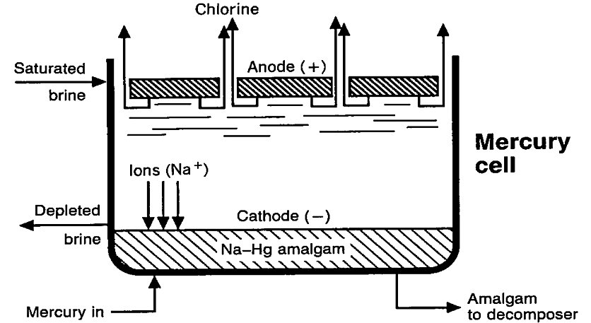
Electric current flowing through the cell decomposes the brine passing through the narrow space between the electrodes, liberating chlorine gas (Cl2) at the anode and metallic sodium (Na) at the cathode. The chlorine gas is accumulated above the anode assembly and is discharged to the purification process. As it is liberated at the surface of the mercury cathode, the sodium immediately forms an amalgam (NaHgx). The concentration of the amalgam is maintained at 0.2–0.4wt-% Na so that the amalgam flows freely. The liquid amalgam flows from the electrolytic cell to a separate reactor, called the decomposer or denuder, where it reacts with water in the presence of a graphite catalyst to form sodium hydroxide and hydrogen gas. The sodium-free mercury is fed back into the cell and is reused[2].
The depleted brine anolyte leaving the cell is saturated with chlorine and must be partially dechlorinated before being returned to the dissolvers[2].
The sodium hydroxide is produced from the decomposer at a concentration of approximately 50wt-%; the maximum value reported is 73wt-%[2].
Mercury cells are usually operated to maintain a 21–22wt-% concentration of salt in the spent brine discharged from the cell. This corresponds to the decomposition of 15–16% of the salt during a single pass. Further salt decomposition to a lower concentration in the brine would decrease brine conductivity, with the attendant loss of electrical efficiency. However, in plants with once-through brine systems, approximately 40% of the salt is electrolysed in the cells[2].
The mercury cell technique has the advantage over the diaphragm and membrane cell techniques that it produces a chlorine gas with nearly no oxygen, and a 50wt-% caustic soda solution. However, mercury cells operate at a higher voltage (3–5V) and current density (7–10kA/m2) than diaphragm and membrane cells and, therefore, use more energy (caustic soda concentration excluded). The technique also requires a pure brine solution with little or no metal contaminants to avoid the risk of explosion through hydrogen generation in the cell. The mercury cell technique inherently gives rise to environmental releases of mercury[2].
Chlor-Alkali Process in a Diaphragm Cell
The diaphragm cell technique differs from the mercury cell technique in that all reactions take place within one cell and the cell effluent contains both dissolved salt and caustic soda. A diaphragm is employed to separate the chlorine liberated at the anode, and the hydrogen and caustic soda produced directly at the cathode (Fig. 2). Without the diaphragm to isolate them, the hydrogen and chlorine would spontaneously ignite and the caustic soda and chlorine would react to form sodium hypochlorite (NaClO), with a further reaction producing sodium chlorate (NaClO3)[2].
Figure 2 - Schematic view of chlorine electrolysis diaphragm cell[2]
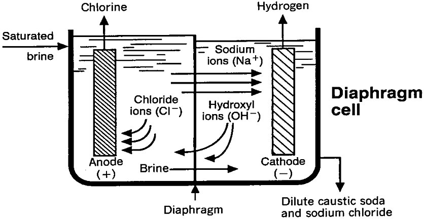
The diaphragm separates the feed brine (anolyte) from the caustic-containing catholyte. Purified brine enters the anode compartment and percolates through the diaphragm into the cathode chamber. The percolation rate is controlled by maintaining a higher liquid level in the anode compartment to establish a positive and carefully controlled hydrostatic head. The percolation rate is controlled to maintain a balance between a low rate, which would produce a desirably high concentration of caustic soda in the catholyte (which provides the cell effluent), and a high rate to limit back-migration of hydroxyl ions from the catholyte to the anolyte, which would decrease the cathode current efficiency[2].
The earliest diaphragms were made of sheets of asbestos paper, but in the late 1920s these were replaced by the deposited asbestos diaphragm. Beginning in the early 1970s, pure asbestos diaphragms began to be replaced by diaphragms containing a minimum of 75 % asbestos and up to 25 % fibrous fluorocarbon polymer with high chemical resistance. These Polymer Modified Asbestos (PMA) diaphragms are more stable, as the polymer stabilises the asbestos, which in turn lowers the cell voltage and also allows for the use of an expandable anode. The development of non-asbestos diaphragms started in the mid-1980s. Two non-asbestos diaphragm systems were commercially available in 2010. The basis of the material used is the same in all asbestos-free diaphragms, i.e. a fluorocarbon polymer, mainly PTFE (polytetrafluoroethylene). The differences lie in the fillers used and the way the hydrophobic PTFE fibres are treated and deposited in order to form a permeable and hydrophilic diaphragm[2].
Diaphragm cells generally produce cell liquor that contains 10–12wt-% NaOH and 15–17wt-% NaCl. Generally, this solution is evaporated to 50wt-% NaOH. The caustic liquour produced may contain lower concentrations of approximately 7wt-% NaCl if it is used directly without further concentration. During evaporation, most of the sodium chloride precipitates, except a residual of approximately 1.0wt-%. The salt generated is very pure and is typically used to make more brine. This high quality sodium chloride is sometimes used as a raw material for mercury or membrane cells[2].
Low concentrations of oxygen (0.5–2.0vol-%) in chlorine are formed by the electrolytic decomposition of water. Furthermore, chlorate is formed in the cell liquor by anodic oxidation and the disproportionation of hypochlorous acid (0.04–0.05wt-% before concentration, ~ 0.1wt-% after concentration)[2].
In the diaphragm cell, saturated brine (approximately 25wt-% NaCl) is decomposed to approximately 50% of its original concentration in a passage through the cell, compared to a 16% decomposition of salt per passage through mercury cells. Heating caused by the passage of a current through the liquids raises the operating temperature of the electrolyte to 80–99ºC[2].
The advantages of diaphragm cells are that the quality requirements for the brine and the electrical energy consumption are low (cell voltage 3–4V; current density 0.5–3kA/m2). However, a high amount of steam may be necessary for the caustic soda concentration, and the quality of the caustic soda and chlorine produced are low[2].
Chlor-Alkali Process in a Membrane Cell
In the membrane cell technique, the anode and cathode are separated by an ion-conducting membrane (Fig. 3). Brine solution flows through the anode compartment, where chloride ions are oxidised to chlorine gas. The sodium ions, together with approximately 3.5 to 4.5 moles of water per mole of sodium, migrate through the membrane to the cathode compartment, which contains a caustic soda solution. The water is electrolysed at the cathode, releasing hydrogen gas and hydroxide ions. The sodium and hydroxide ions combine to produce caustic soda, which is typically kept at 32 ± 1wt-% in the cell by diluting a part of the product stream with demineralised water to a concentration of approximately 30wt-% and subsequent recycling to the catholyte inlet. Caustic soda is continuously removed from the circuit. Depleted brine is discharged from the anode compartment and resaturated with salt. The membrane largely prevents the migration of chloride ions from the anode compartment to the cathode compartment; therefore, the caustic soda solution produced contains little sodium chloride (i.e. approximately 50mg/l). Back-migration of hydroxide is also largely prevented by the membrane but nevertheless takes place to a certain extent and increases the formation of oxygen, hypochlorite and chlorate in the anode compartment, thereby resulting in a loss of current efficiency of 3–7% with respect to caustic soda production[2].
Figure 3 - Schematic view of chlorine electrolysis membrane cell[2]
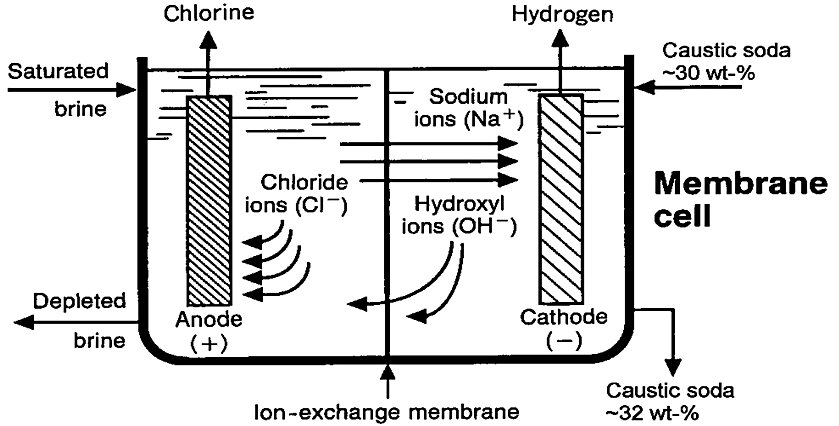
The membranes used in the chlor-alkali industry are commonly made of perfluorinated polymers. The membranes may have one to three layers, but generally consist of two layers. One of these layers consists of a perfluorinated polymer with substituted carboxylic groups and is adjacent to the cathodic side. The other layer consists of a perfluorinated polymer with substituted sulphonic groups and is adjacent to the anodic side. The carboxylate layer exhibits a high selectivity for the transport of sodium and potassium ions and largely prevents the transport of hydroxide, chloride, hypochlorite, and chlorate ions, while the sulphonate layer ensures good mechanical strength and a high electrical conductivity. To give the membrane additional mechanical strength, it is generally reinforced with PTFE fibres. The membranes must remain stable while being exposed to chlorine on one side and a strong caustic solution on the other. Commercially available membranes are optimised for use in a specific strength of caustic. Depending on the particular design, membrane sizes range from 0.2 to 5 m2. The general economic lifetime of chlor-alkali membranes is approximately three to five years[2].
Some electrolysers produce a more diluted 23–24wt-% caustic soda. In this case, the caustic entering the cell has a concentration of approximately 20–21wt-% and the heat of the electrolysis can be used to concentrate the 23–24wt-% caustic solution to 32–34wt-%. The overall energy efficiency is comparable to the aforementioned process with the 32wt-% caustic solution but more equipment is required for the caustic evaporation. On the other hand, simpler and cheaper construction materials can be used in the caustic circuit around the membrane cells[2].
Generally, the caustic produced in a concentration of 30–33wt-% is concentrated to the usual commercial standard concentration of 50wt-% by evaporation (using steam). Another possibility is to use the caustic produced in the membrane cells as feed to the decomposers of mercury cells[2].
The concentration of sodium chlorate in the produced caustic soda typically ranges from ≤ 10 to 50mg/kg. The level depends on the membrane characteristics, the operational current density and the chlorate levels in the brine. The chlorine produced in membrane cells contains low concentrations of oxygen (0.5–2.0 vol-%). The formation of oxygen and chlorate can be depressed by selecting an anode coating with suitable characteristics and/or by decreasing the pH in the anode compartment[2].
Brine depletion in membrane cells is two or three times greater than in mercury cells, which allows the brine system to be smaller, resulting in significantly lower recycling rates and less equipment needed compared to mercury cell plants of the same capacity[2].
The membrane cell technique has the advantage of producing a very pure caustic soda solution and of using less energy than the other techniques. In addition, the membrane cell technique uses neither mercury, which is classified as very toxic, nor asbestos, which is classified as toxic (carcinogenic). Disadvantages of the membrane cell technique are that the caustic soda produced may need to be evaporated to increase its concentration and, for some applications, the chlorine gas produced needs to be processed to remove oxygen, usually by liquefaction and evaporation. Furthermore, the brine entering a membrane cell must be of a very high purity, which requires additional purification steps prior to electrolysis[2].
References
- EPA, Chlor-Alkali.
- T. Brinkmann et al. Best Available Techniques (BAT) Reference Document for the Production of Chlor-alkali. Industrial Emissions Directive 2010/75/EU. EUR 26844. Luxembourg: Publications Office of the European Union; 2014. JRC91156.


