The Riedl-Pfleiderer Process, also known as the Anthraquinone Auto-Oxidation (AO) Process, is the predominant industrial method for hydrogen peroxide (H2O2) production worldwide, accounting for over 95% of global production. Developed by Georg Pfleiderer and Hans-Joachim Riedl at IG Farben between 1935 and 1945, this process was first commercialized by E.I. DuPont de Nemours in 1953. The process has since been continuously refined and remains the technological backbone of the hydrogen peroxide industry.
Historical Development
The development of the Riedel-Pfleiderer process represented a significant advancement over earlier hydrogen peroxide production methods. Prior to this innovation, hydrogen peroxide was primarily produced through the Thenard process (using barium peroxide) or electrochemical methods, both of which were limited in scale and efficiency. The breakthrough came from Pfleiderer's work on polynuclear hydroquinones, building upon earlier research by Riedl on autoxidizable compounds. German company BASF developed the process to achieve a monthly output of 30 MT (based on 100% H2O2) by 1945.
Process Overview and Chemistry
Fundamental Principle
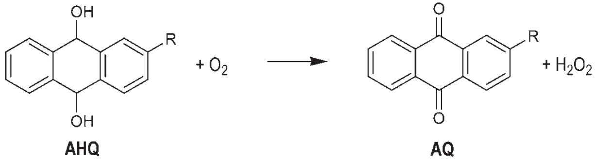
The Riedel-Pfleiderer process operates on a cyclical reduction-oxidation mechanism involving alkylated anthraquinones as organic carriers. The overall net reaction is:
H2 + O2 → H2O2
This is achieved through a two-step cycle:
-
Hydrogenation (Reduction):
-
Oxidation (Auto-oxidation):
Working Solution Composition
The working solution is the heart of the process, consisting of:
Active Compounds:
- 2-Ethylanthraquinone (EAQ): Most commonly used (30% of active quinones)
- 2-Ethyl-5,6,7,8-tetrahydroanthraquinone (THEAQ): (70% of active quinones)
- Alternative quinones: 2-tert-butyl-, 2-tert-amyl-, or 2-sec-amylanthraquinones
Solvent System:
- Quinone-friendly solvents: Aromatic hydrocarbons (C9-C12), trimethylbenzene (TMB), methylnaphthalene, tert-butylbenzene
- Hydroquinone-friendly solvents: Trioctyl phosphate (TOP), nonyl alcohols, tetrabutylurea (TBU), alkylcyclohexanol acetates
- Typical ratio: 50-80% aromatic solvents, 20-50% polar solvents
The solvent system must satisfy multiple requirements: low water solubility, chemical stability, good dissolving properties for both quinone forms, low volatility, and appropriate density for phase separation.
Detailed Process Description
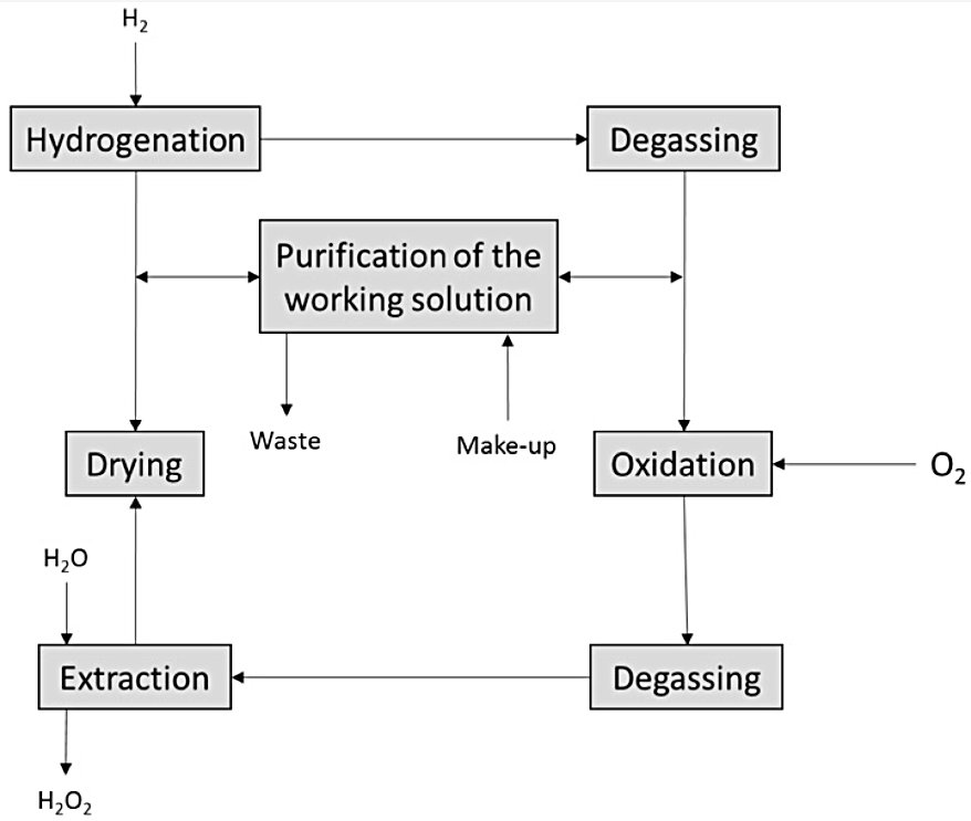
Simplified Riedl-Pfleiderer Process Block Flow Diagram
Step 1: Hydrogenation (Reduction)
Reactor Design:
- Fixed-bed reactors: Trickle-bed or packed-bed configurations with immobilized Pd catalyst
- Slurry reactors: Fluidized-bed or stirred-tank reactors with suspended catalyst particles
- Continuous stirred-tank reactors (CSTR): For laboratory and pilot-scale operations
Operating Conditions:
- Temperature: 40-70°C (optimal around 50°C)
- Pressure: 2-5 bar H2 pressure
- Conversion: Limited to 50-70% to minimize side reactions
- Residence time: 5-30 minutes depending on reactor type
- Catalyst System:
- Active metal: Palladium (preferred) or Raney nickel
- Support: Activated alumina, activated carbon, or ion-exchange resins
- Particle size: 1-5 mm for fixed-bed, 50-200 μm for slurry systems
- Loading: 0.1-1.0 wt% Pd on support
Reaction Mechanism:
The hydrogenation follows a Rideal-Eley mechanism where hydrogen dissociatively adsorbs on palladium, while tetrahydroanthraquinone (THEAQ) reacts from solution:
-
H2 + 2 Pd → 2 Pd-H (surface)
-
THEAQ + 2 Pd-H → THEAQH2 + 2 Pd
Side Reactions and Catalyst Deactivation:
- Reversible poisoning: Water adsorption on Pd sites (30% activity loss in 1-2 days)
- Irreversible poisoning: Condensation of partially hydrogenated anthraquinones
- Ring hydrogenation: Formation of octahydro derivatives (H8EAQH2) which are inactive
- Catalyst regeneration: Required every 3-6 months in industrial operations
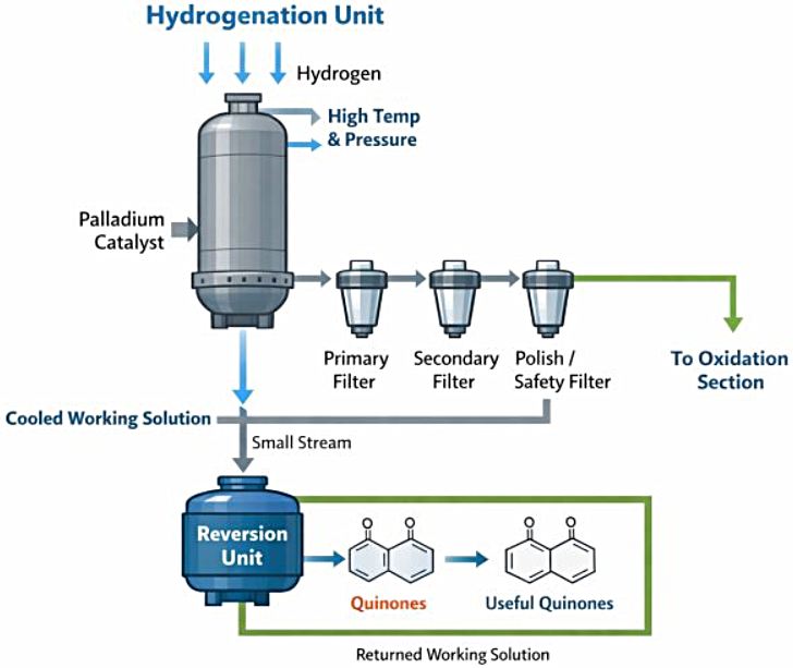
Post-Reaction Working Solution Handling:
- Cooling: After the hydrogenation reactor, the working solution is cooled before proceeding to catalyst filtration
- Filtration: The working solution passes through a three-stage filtration train — primary, secondary, and polish/safety filters — to remove Pd catalyst particles before the solution enters the oxidation section (Pd carry-over into the oxidation stage promotes H2O2 decomposition and must be controlled to near-zero levels)
- Reversion Unit: A small side stream of the cooled working solution is continuously diverted to a Reversion Unit, where labile degradation products formed during hydrogenation — primarily epoxides and partially hydrogenated quinone derivatives — are reconverted to active quinone species. This continuous in-line reversion maintains working-solution health between periodic regeneration cycles and reduces the load on the standalone regeneration unit (Step 5).
Filtration and reversion units
Step 2: Oxidation (Auto-oxidation)
Reactor Design:
- Bubble column reactors: Continuous countercurrent air-liquid contact
- Packed columns: Multi-stage cascade systems (e.g., BASF's four-column series)
- Co-current oxidation: Single-column systems with air and solution flowing together
Operating Conditions:
- Temperature: 30-80°C (optimal 40-70°C)
- Pressure: Atmospheric to 5 bar
- Oxygen partial pressure: 0.2-3 atm (optimal 0.5-1.5 atm)
- Residence time: 1-3 hours
- Air flow: High enough to maintain good mixing
Reaction Kinetics:
The oxidation follows second-order kinetics:
- Rate law: r = k[THEAQH2][O2]
- Enhancement factor: ≈ 1 (moderately slow reaction)
- Mass transfer: Consecutive with chemical reaction
By-product Formation:
- Epoxides: Formed during oxidation, particularly at higher temperatures
- Anthrones/Dianthrones: Result from tautomerization reactions
- Oxanthrones: Formed through side oxidation pathways
Step 3: Extraction
Process Design:
- Countercurrent extraction: Pulsating packed towers or mixer-settler units
- Extraction efficiency: 98% H2O2 recovery
- Solvent: Demineralized water
- Product concentration: 15-35 wt% H2O2 solution
Operating Conditions:
- Temperature: 25-40°C
- Pressure: Atmospheric
- Water-to-organic ratio: 1:3 to 1:5 (volume basis)
- Number of stages: 3-8 theoretical stages
Step 4: Purification and Concentration
Purification Steps:
- Activated carbon treatment: Removal of organic impurities
- Ion exchange: Removal of metal ions and stabilization
- Distillation: Concentration to 50-70 wt% H2O2
Concentration Methods:
- Vacuum distillation: Primary concentration method
- Fractional distillation: For high-purity grades
- Crystallization: For ultra-pure applications
Step 5: Working Solution Regeneration
Drying Step:
- Objective: Remove water content to 0.1-0.5 wt%
- Methods: Vacuum drying, molecular sieves, or azeotropic distillation
Regeneration Process:
- Catalyst: Alkaline alumina or silica-alumina (4% NaOH on Al2O3)
- Operating conditions: 100-150°C, packed-bed reactor
- Reactions promoted:
- THEAQ dehydrogenation: Converts degraded quinones back to active forms
- Epoxide reconversion: Regenerates active quinones from epoxides
- Acid neutralization: Removes free acidity from working solution
Regeneration Reactions:
- Dehydrogenation: H6THEAQ → THEAQ + 3 H2
- Epoxide conversion: Epoxides → Active quinones
- Tar removal: Preferential adsorption on alkaline catalyst
Technology Owners and Licensors
Historical Development
- Original developers: Georg Pfleiderer and Hans-Joachim Riedl (IG Farben)
- First commercial plant: E.I. DuPont de Nemours (1953)
- Early industrial adopters: BASF, Degussa, Solvay
Current Technology Providers
- Solvay SA: Major licensor and operator of AO process technology
- BASF SE: Continues to operate and license the technology
- Evonik Industries: Provides catalyst and process technology
- Chinese companies: Multiple domestic technology providers for local markets
Equipment Manufacturers
- Reactor systems: Specialized chemical engineering companies
- Catalysts: Solvay, BASF, Johnson Matthey, Evonik
- Process equipment: Alfa Laval, Sulzer, Koch-Glitsch
Process Variants and Improvements
All-Tetra Process
A specialized variant using a mixture of 30% EAQ and 70% THEAQ, designed for:
- Higher selectivity: Reduced side reactions
- Improved stability: Better catalyst performance
- Enhanced efficiency: Higher H2O2 productivity per cycle
Fixed-Bed vs. Fluidized-Bed Reactors
- Fixed-bed: More common, easier operation, lower maintenance
- Fluidized-bed: Better heat transfer, uniform catalyst distribution, higher productivity
- Slurry systems: Easier catalyst handling, better temperature control
Modern Improvements
- Micro-packed-bed reactors: 25× higher space-time yield than conventional reactors
- Membrane separation: Enhanced extraction efficiency and organic retention
- Process intensification: Reduced equipment size and energy consumption
Economic and Environmental Considerations
Capital Investment
- Plant capacity: 40,000-330,000 MT/year typical industrial scale
- Equipment costs: Dominated by reactor systems, extraction columns, and distillation units
- Working capital: Significant inventory of working solution and catalysts
Operating Costs
- Raw materials: Hydrogen (60-70%), oxygen/air (10-15%), quinones and solvents (15-20%)
- Utilities: Energy for compression, heating, and cooling
- Catalyst replacement: Regular Pd catalyst makeup and regeneration
- Maintenance: Working solution purification and regeneration
Environmental Impact
- Waste streams: Spent working solution, catalyst disposal, organic emissions
- Energy consumption: Significant for hydrogen production and compression
- Safety considerations: Hydrogen handling, organic solvent management
Process Advantages and Limitations
Advantages
- High efficiency: 95%+ conversion of H2 and O2 to H2O2
- Scalability: Proven from pilot to mega-scale (330,000 MT/year)
- Product purity: Achievable grades from 35% to 70% H2O2
- Technological maturity: Decades of industrial experience and optimization
Limitations
- Complex chemistry: Multiple side reactions and catalyst deactivation
- High capital investment: Large-scale equipment requirements
- Operating complexity: Requires skilled operators and process control
- Environmental concerns: Organic working solution management and disposal
References
- Synthesis of hydrogen peroxide via antraquinone - Eurochem Engineering
- Anthraquinone Process for Production of Hydrogen Peroxide - Look for Chemicals
- Hydrogen peroxide; anthraquinone process; production mix, at plant; 50%; H2O2, Location: DE - Germany, Reference year: 2019 - 2022, Global LCA Data Access
- Ranganathan, S.; Sieber, V. Recent Advances in the Direct Synthesis of Hydrogen Peroxide Using Chemical Catalysis—A Review. Catalysts 2018, 8, 379. DOI: 10.3390/catal8090379
- J. L. G. Fierro et al., Hydrogen Peroxide Synthesis: An Outlook beyond the Anthraquinone Process, Angew. Chem. Int. Ed. 2006, 45, 6962 – 6984, DOI: 10.1002/anie.200503779
- Takashi Kamachi et al., Computational Exploration of the Mechanism of the Hydrogenation Step of the Anthraquinone Process for Hydrogen Peroxide Production, J. Phys. Chem. C 2015, 119, 16, 8748–8754, DOI: 10.1021/acs.jpcc.5b01325
- Qunlai Chen, Development of an anthraquinone process for the production of hydrogen peroxide in a trickle bed reactor—From bench scale to industrial scale, Vol. 47, Issue 5, 2008, Pp 787-792, ISSN 0255-2701, DOI: 10.1016/j.cep.2006.12.012
- Rathin Datta et al., Process for the production of hydrogen peroxide, United States patent US5662878A, Patent filed: Apr 25, 1996, University of Chicago
- Apr 11, 2022 - How H2O2 is produced: The Anthraquinone Process - Chongqing Hesheng Longgang Technology Co., Ltd./Jianfeng Chemical Co., Ltd.
- Baldassarre Venezia, Nov 2021 - Thesis: Reactor Designs for Safe and Intensified Hydrogenations and Oxidations: From Micro- to Membrane Reactors - University College London
- Wentao Shi et al., Working solution for producing hydrogen peroxide by anthraquinone process, Chinese Patent CN105600755A, Patent filed: Mar 17, 2016, China Tianchen Engineering Corp, Tianjin Tianchen Green Energy Resources Engineering Technology and Development Co Ltd
- Richard Haase, Methods and processes of hydrogen peroxide production, United States Patent US20040126313A1, Patent filed: Jun 24, 2003
- Peng A. (Mar 25, 2026). Linkedin post: The Hydrogenation Unit in Hydrogen Peroxide (H2O2) Production — Why It Matters. HeBang Engineering Co.,Ltd