The HCl electrolysis process converts hydrochloric acid into chlorine and hydrogen through electrochemical reactions, primarily used for chlorine recovery in chemical manufacturing.
Three distinct technologies are commercially available, each with fundamentally different operating principles, equipment requirements, and product streams. This process enables the recycling of chlorine in chemical manufacturing, particularly in isocyanate production plants, providing both economic and environmental benefits.
Process Chemistry and Technology Comparison
Fundamental Electrochemical Reactions
Base reaction (all technologies): 2 HCl(aq) → Cl2(g) + H2(g)
Technology-specific cathode reactions:
- Diaphragm/Membrane cells: 2 H+ + 2 e- → H2 (produces hydrogen)
- ODC cells: O2 + 4 H+ + 4 e- → 2 H2O (consumes oxygen, no hydrogen production)
Figure 1 - HCl electrolysis via the oxygen-depolarized cathode process[1]
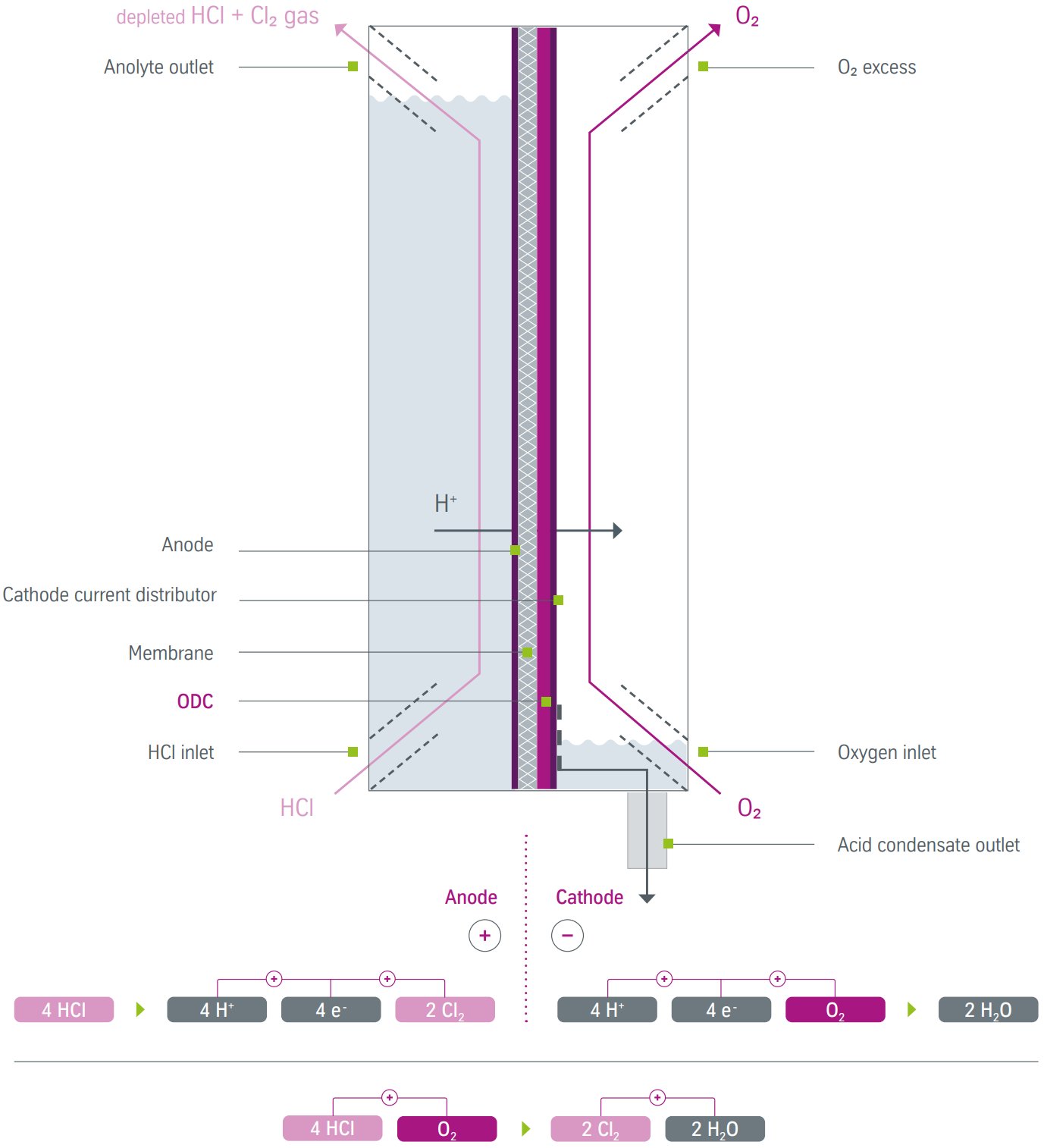
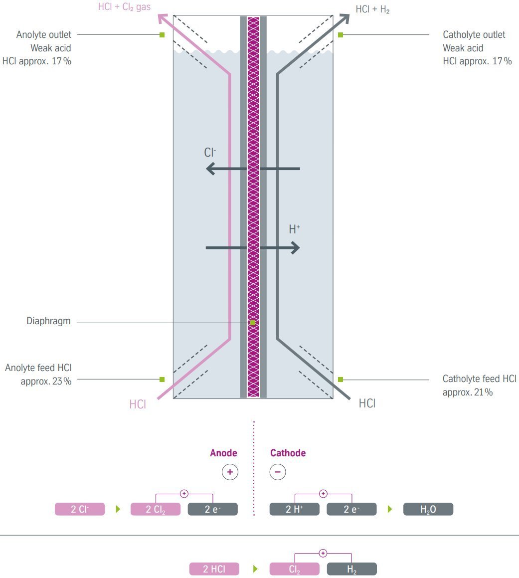
Figure 2 - HCl electrolysis via the diaphragm process[1]
Technology Performance Summary
| Technology |
Energy Consumption |
Products |
Key Advantages |
Applications |
|
ODC
Process
|
733-1070
kWh/t Cl2 |
Cl2 only |
30% energy savings, no H2 safety issues |
When H2 not needed |
| Diaphragm Cell |
1670
kWh/t Cl2 |
Cl2 + H2 |
Lower capital cost, H2 co-production |
When H2 required |
| Membrane Cell |
1900-2100
kWh/t Cl2 |
Cl2 + H2 |
Highest purity, complete gas separation |
High purity requirements |
Major Process Technologies
1. Oxygen Depolarized Cathode (ODC) Technology
Process principle: Oxygen reduction replaces hydrogen evolution, eliminating H2 production and reducing cell voltage by ~1V.
Technology development: Jointly developed by thyssenkrupp nucera, Covestro, and De Nora, with first world-scale plant operational in Tarragona, Spain (2023).
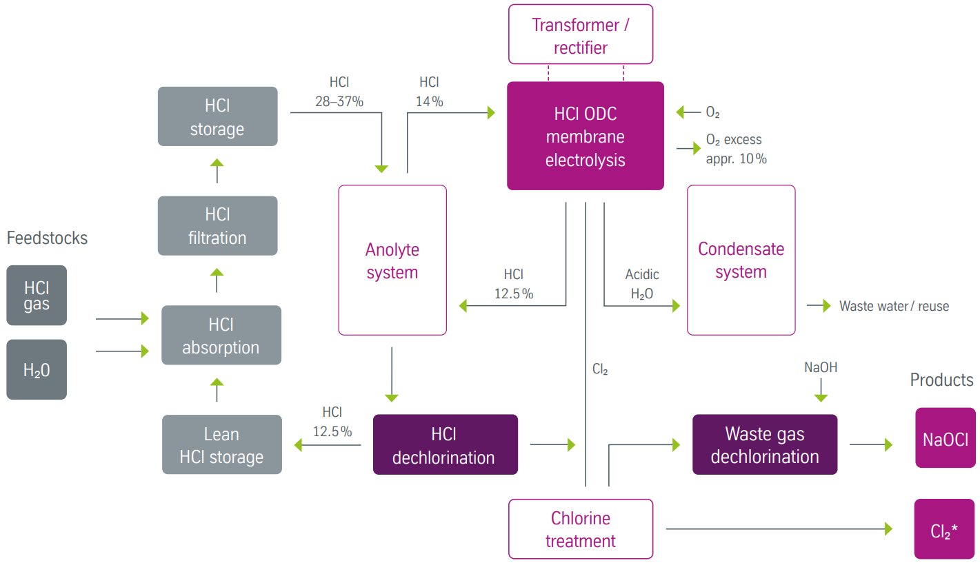
Figure 3 - HCl electrolysis ODC process block flow diagram[1]
Operating parameters:
- Current density: 4-6 kA/m²
- Cell voltage: 0.9-1.4 V
- Energy consumption: 733-1070 kWh/t Cl2
- Operating pressure: 200 mbarg anode side
- Temperature: 45-75°C
Unique equipment requirements:
- Oxygen supply system with flow control
- Gas diffusion electrodes with precious metal catalysts
- Single acid circuit - no separate anolyte/catholyte
- Oxygen-consuming cathode infrastructure
2. Diaphragm Cell Technology
Process principle: Porous diaphragm allows controlled liquid flow while separating electrode compartments, producing both Cl2 and H2.
Technology heritage: Developed jointly by former Hoechst AG, Bayer AG, and thyssenkrupp nucera.
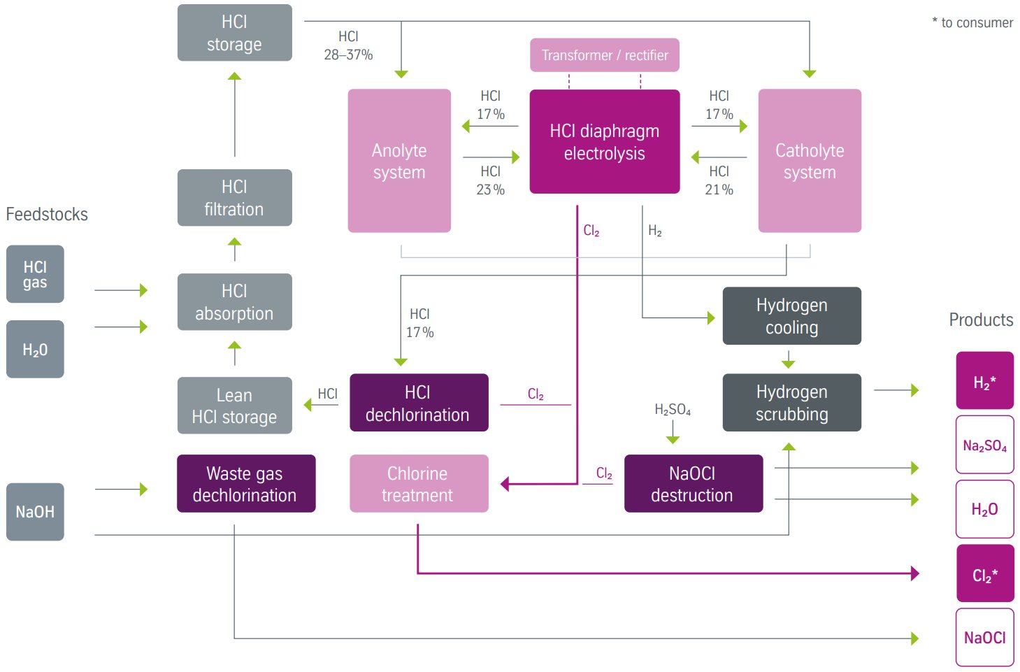
Figure 4 - HCl electrolysis diaphragm process block flow diagram[1]
Operating parameters:
- Current density: 4-6 kA/m²
- Cell voltage: 1.4-2.2 V
- Energy consumption: 1670 kWh/t Cl2
- Anolyte concentration: 23 wt% HCl
- Catholyte concentration: 21 wt% HCl
- Depleted acid: 17 wt% HCl from both compartments
Specific equipment requirements:
- Dual acid preparation systems for anolyte and catholyte
- Separate gas handling for Cl2 and H2 streams
- Diaphragm permeability control systems
- Hydrogen safety systems to prevent H2/Cl2 mixing
3. Membrane Cell Technology
Process principle: Ion-selective membrane allows only H+ transport, producing high-purity Cl2 and H2 in completely separated streams.
Technology status: Dominant technology globally due to superior efficiency and environmental compliance.
Operating parameters:
- Cell voltage: 1.9-2.1 V
- Energy consumption: 1900-2100 kWh/t Cl2
- Feed acid: 30 wt% HCl to catholyte
- Acid transfer: ~21 wt% HCl from catholyte to anolyte
- Depleted acid: ~18 wt% HCl from anolyte
Equipment characteristics:
- Connected dual circuits with acid overflow between compartments
- Complete gas separation - zero crossover risk
- High-purity product streams
- Cation-exchange membranes (typically perfluorinated)
Plant Configuration and Process Flow
ODC Process Configuration
Single acid circuit design:
- Anolyte tank with automatic concentration control (14 wt% HCl)
- Feed preparation via dilution of 37 wt% acid with depleted 12.5 wt% acid
- No separate catholyte circuit - oxygen supplied directly to cathode
- Simplified acid recycle - single depleted stream to absorption unit
Oxygen supply system:
- Dedicated oxygen generation or external supply
- Flow control and distribution to cathode compartments
- Pressure regulation for optimal electrode contact
Diaphragm Cell Configuration
Dual acid preparation systems:
- Anolyte preparation: 23 wt% HCl feed from concentrated acid mixing
- Catholyte preparation: 21 wt% HCl from independent dilution system
- Separate circulation pumps for each acid circuit
- Depleted acid collection: Both streams at 17 wt% HCl
Diaphragm flow control:
- Liquid level differential maintained between compartments
- Controlled permeation through PVC/PVDF diaphragm
- Hydrodynamic pressure balance to prevent gas crossover
Dual gas handling:
- Separate chlorine and hydrogen collection systems
- Independent gas treatment and purification
- Safety systems to prevent explosive gas mixing
Membrane Cell Configuration
Connected acid circuits:
- Primary feed: 30 wt% HCl to catholyte compartment
- Inter-compartment transfer: Overflow from catholyte to anolyte
- Depleted acid recovery: Single stream from anolyte at ~18 wt% HCl
Complete stream separation:
- Impermeable membrane prevents liquid crossover
- Independent gas collection with zero mixing risk
- High-purity products suitable for demanding applications
HCl Absorption and Pretreatment (All Technologies)
Common absorption system:
- Anhydrous HCl gas from isocyanate production enters absorption
- Isothermal absorption in falling-film columns with cooling
- Concentration control to produce 28-37 wt% HCl feed
- Impurity removal via stripping and filtration
Key equipment:
- Falling-film absorber with shell-side cooling
- Stripping column for organic removal
- Active carbon filters for trace impurities
- Heat exchangers for temperature control
Process Control and Operating Parameters
Common control systems:
- Concentration monitoring and automatic adjustment
- Temperature control via cooling water circuits
- Pressure management for optimal performance
- Current density optimization for efficiency
Technology-specific controls:
- ODC: Oxygen flow and pressure regulation
- Diaphragm: Dual acid circuit balancing and gas separation
- Membrane: Acid overflow control and membrane integrity
Technology Selection Criteria
Energy Efficiency Priorities
ODC process preferred for pure chlorine recovery with maximum energy efficiency:
- Energy cost is critical (30% savings vs diaphragm)
- Hydrogen not required for other processes
- Environmental compliance emphasized
- High chlorine purity needed
Co-product Requirements
Diaphragm cells chosen when hydrogen utilization is economically attractive:
- Hydrogen needed for downstream processes
- Lower capital investment required
- Proven reliability prioritized
- Flexible operation desired
Membrane cells selected for highest reliability and regulatory compliance:
- Highest product purity requirements
- Complete gas separation mandatory
- Environmental regulations compliance
- Long-term operation optimization
Integration with Isocyanate Plants
Process integration benefits from chlorine recycle economics:
- HCl from phosgene reactions feeds electrolysis
- Recovered chlorine returns to phosgene production
- Elimination of HCl disposal costs
- Reduced external chlorine purchases
References
- thyssenkrupp nucera. Aug 2023. HCl Brochure.
- thyssenkrupp nucera. Hydrochloric Acid Solutions.
- MarketsandMarkets. Aug 2025. Report CH9485: Hydrochloric Acid Electrolysis Market.
- R Kuwertz et al. Energy-efficient chlorine production by gas-phase HCl electrolysis with oxygen depolarized cathode. Electrochem. Commun., 2013, Vol. 34, pp 320-322. ISSN 1388-2481. DOI 10.1016/j.elecom.2013.07.035.
- H2TECH. Feb 27, 2023. Covestro and thyssenkrupp nucera collaborate to develop energy-efficient electrolysis technology.
- Covestro. Feb 6, 2023. Covestro successfully starts up a new world-scale chlorine plant in Tarragona.
- F. Mohammadi et al. Aqueous HCl electrolysis utilizing an oxygen reducing cathode. Chem. Eng. J., 2009, Vol. 155, 3, 757-762. ISSN 1385-8947. DOI 10.1016/j.cej.2009.08.030.
- B.A. Maloney. United States patent US5630930A: Method for starting a chlor-alkali diaphragm cell. Priority date Jul 26, 1995. Application filed by PPG Industries Inc.
- F.R. Minz. United States patent US4725341A: Process for performing HCl-membrane electrolysis. Priority date: Jan 13, 1987. Application filed by Bayer AG.
- Eurochlor. Membrane Cell Process.
- De Dietrich. HCl Treatment.
- T.F. Ukolowicz, S.F. Muscarella. United States patent: Heat exchanger for heating hydrochloric acid pickling solution, a system and method for pickling, and a method of manufacturing steel products. Priority date Dec 12, 2023. Assignee: Titan Metal Fabricators.
- Research And Markets. Aug 2025. Report ID 6167350: Hydrochloric Acid Electrolysis Market.
- Clean Development Mechanism (CDM). May 14, 2014. CDM-MP63-A01 - Draft Large-scale Methodology AM00XX: Shift from electrolytic to catalytic process for recycling of chlorine from hydrogen chloride gas in isocyanate plants.
- M. Ikeguchi et al. Hydrogen Halide Oxidation Process for Sustainable Halogen Recycling. Sumitomo Kagaku, 2021, Report 1, 1-13.