Definition and Purpose
The Unsaturated Gas Plant (USGP) — also called the FCC Gas Recovery Unit, or Cracked Gas Plant — separates the contents of the gas and liquid streams coming from the overhead of the Fluid Catalytic Cracking Unit (FCC) and the Delayed Coking Unit (DCKU) into pressurized noncondensables (C1–C2 with trace C3s from the wet gas compressors) and unstabilized naphtha (C3–C12) from the main-column overhead systems.[1] The plant is termed “unsaturated” because the cracked streams it processes are rich in olefins — molecules containing carbon–carbon double bonds (butylene rather than butane) — produced by the hydrogen-poor thermal cracking of the coker and catalytic cracking of the FCC riser.[1][4]
Its purpose is threefold:
Compared with the sister Saturated Gas Plant, three differences define the USGP’s design: the volume of LPG and noncondensables entering the plant is many times greater, so the front-end separation and sulfur-removal processes are much more robust; the propylene product is a premium chemical-plant feed; and the butylene product supplies the alkylation unit with high-octane gasoline blending component.[1] Segregating the two gas plants allows each to be optimized independently — olefin-recovery economics on the cracked side, simple robust LPG/naphtha recovery on the saturated side — a configuration documented in the Chevron Salt Lake City plant-wide energy assessment, where constructing a dedicated saturated gas plant avoided reprocessing saturated gas in the alkylation plant and saved an estimated 20,000 MMBtu/yr of fuel.[5] Both plants share the same core architecture of wet-gas compression, absorption, stripping and debutanization, differing in feed slate, compression duty and product disposition.[10]
Feed Sources and Characteristics
| Feed Source |
Composition Notes |
| FCCU wet gas (via the FCCU wet gas compressor) |
Pressurized noncondensables, mainly C1–C2 with entrained LPG components[1] |
| FCCU main-column overhead condensate |
Unstabilized cat naphtha (C3–C12) containing dissolved C3/C4, including propylene[1][3] |
| DCKU wet gas (via the coker wet gas compressor) |
Pressurized noncondensables, C1–C2, routed to the gas plant train[1][2] |
| DCKU main-column overhead |
Unstabilized coker naphtha (C3–C12); higher sulfur and nitrogen species than FCC gas[1][2] |
Process Configuration
1. Feed Separation and Stripping (D-21, T-4)
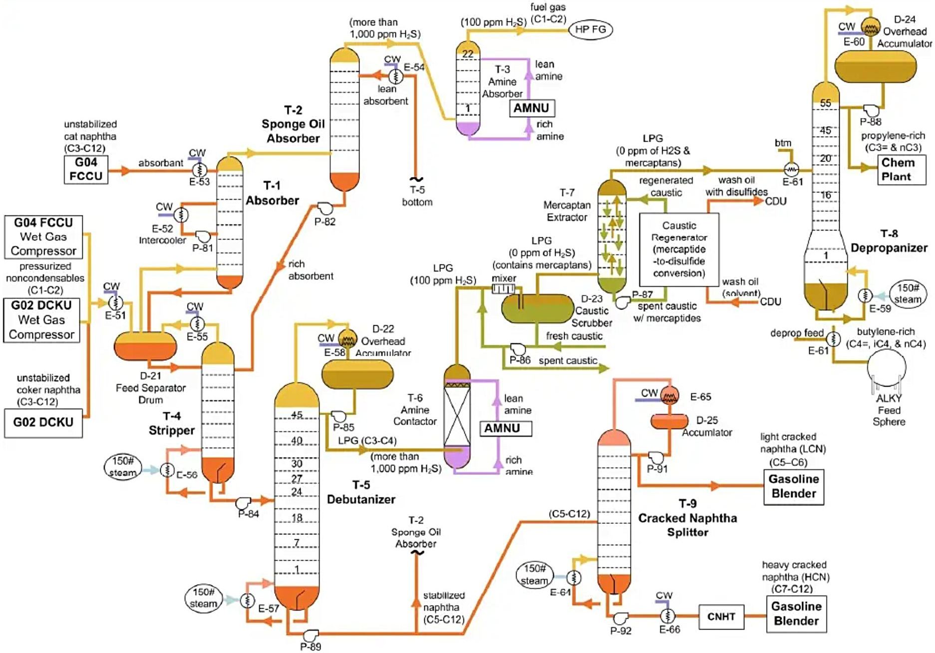
Wet gas from the FCCU and coker passes through a cooler (E-51) that condenses entrained LPG components. The D-21 Feed Separator Drum stabilizes the liquid flow into the top of the T-4 Stripper: its liquid (LPG plus naphtha) is pressured into the stripper, while its gas — primarily noncondensables (C1–C2) with entrained LPG — flows forward to absorption. The T-4 Stripper is a heat-driven stripper that removes entrained noncondensables from the liquid hydrocarbon phase into the gas phase, out of the tower overhead and back into D-21.[1]
2. Absorption Train (T-1, T-2, T-3)
The T-1 Absorber employs cooled cat naphtha as absorbent to absorb the majority of the entrained LPG from the gas; an intercooler pumparound facilitates the absorption process. The T-2 Sponge Oil Absorber then contacts the gas with lean (stabilized) naphtha as sponge oil to remove all remaining entrained LPG from the fuel gas. The T-3 Amine Absorber decreases the H2S content of the resulting high-pressure fuel gas from over 1,000 ppm to less than 100 ppm; the treated fuel gas (C1–C2) leaves to the high-pressure fuel gas header.[1] Sponge-oil circulation rate is a key recovery-economics variable, and patent literature documents design improvements that reduce the sponge-oil requirement for a given LPG recovery.[6]
3. Debutanizing and LPG Treating (T-5, T-6, D-23, T-7)
The T-5 Debutanizer employs basic distillation to provide an LPG-rich overhead product with a typical purity of over 95% (less than 5% C5 content) and a naphtha-rich bottoms product, also typically over 95% purity (less than 5% C4 content). The LPG then passes the standard treating sequence: the T-6 Amine Contactor decreases H2S content to less than 100 ppm; the D-23 Caustic Scrubber employs caustic scrubbing to take H2S to zero (sodium sulfide, Na2S, remains in the caustic phase, so continuous fresh-caustic and spent-caustic flows maintain caustic strength); and the T-7 Mercaptan Extractor extracts mercaptans — sulfur-bearing LPG hydrocarbons — by converting them to mercaptides that pass from the LPG phase into the caustic phase.[1]
4. LPG Splitting and Naphtha Splitting (T-8, T-9)
The T-8 Depropanizer provides a propylene-rich overhead product with a typical purity of over 97% (less than 3% C4 content) and a butylene-rich, isobutane-rich bottoms product, also typically over 97% purity (less than 3% C3 content). The T-9 Cracked Naphtha Splitter separates the stabilized cracked naphtha into light cracked naphtha (LCN, C5–C6) overhead with a typical purity of over 90% (less than 10% C7 content) and heavy cracked naphtha (HCN, C7–C12) bottoms, also typically over 90% purity (less than 10% C6 content).[1]
5. Common-Process Foundations
The handbook’s operators’ guide anchors each USGP function in the refinery’s common process concepts: basic distillation (debutanizer, depropanizer, naphtha splitter), heat-driven stripping (T-4), hydrocarbon absorption (T-1, T-2), amine absorption and regeneration (T-3, T-6), and caustic scrubbing with mercaptan extraction (D-23, T-7).[1][4]
Product Slate and Destinations
| Stream |
Typical Destination |
| Fuel gas (C1–C2, <100 ppm H2S) |
High-pressure fuel gas header; optionally hydrogen/ethylene recovery in petrochemical-integrated sites[1][7] |
| Propylene-rich C3=/C3 (depropanizer overhead) |
Chemical plant — key feedstock for plastics production[1] |
| Butylene-rich C4= + isobutane (depropanizer bottoms) |
Alkylation Unit — high-octane alkylate gasoline blending component[1] |
| Light cracked naphtha (LCN, C5–C6) |
Gasoline blender directly — low-sulfur component with a RON of 86 in the generic refinery[1] |
| Heavy cracked naphtha (HCN, C7–C12) |
Cracked Naphtha Hydrotreater (CNHT) to reduce sulfur before gasoline blending[1] |
Distinction from the Saturated Gas Plant
| Feature |
Unsaturated (Cracked) Gas Plant |
Saturated Gas Plant |
| Feed sources |
FCCU and DCKU overhead systems (wet gas compressors + unstabilized naphtha)[1] |
CDU/VDU, hydrotreaters, hydrocrackers, reformers |
| Olefin content |
High — olefin molecules with double bonds (propylene, butylenes, diolefins)[1][4] |
Negligible — saturated molecules with single bonds only |
| Throughput character |
LPG and noncondensable volumes many times greater than the SGP; front-end separation and sulfur removal correspondingly more robust[1] |
Smaller light-ends volumes |
| Primary value driver |
Propylene recovery to the chemical plant; butylenes to alkylation[1][9] |
LPG and naphtha recovery efficiency |
| Compression duty |
Wet gas, fouling-prone (diolefin polymerization, NOx gum risk)[7] |
Conventional |
| Naphtha product |
Cracked naphtha split into LCN (direct to blender) and HCN (to CNHT)[1] |
Stabilized virgin naphtha to hydrotreating/reforming |
| Shared architecture |
Both plants share wet-gas compression, absorption, sponge absorption, heat-driven stripping and debutanization[10] |
— |
Role in the Integrated Refinery–Petrochemical Complex
In petrochemical-oriented configurations the USGP is the refinery’s gateway for chemical-grade propylene: FCC propylene-yield increases (higher severity, propylene-maximizing catalysts) push more olefin through the gas plant, and enhanced absorber designs raise recovery beyond the conventional unstabilized-naphtha limit.[8][9] Extended configurations recover ethylene and hydrogen from FCC off-gas, effectively turning the gas plant into a partial olefins-recovery unit serving both fuel and petrochemical product pools.[7]
Process Flow Shown in the Source Diagram
The functional process flow cited as reference [1] (Figure G06-2) draws: FCCU and DCKU wet-gas compressor feeds labelled C1–C2 and unstabilized naphtha feeds (cat naphtha and coker naphtha, C3–C12) entering D-21 Feed Separator and T-4 Stripper; the absorption train T-1 Absorber, T-2 Sponge Oil Absorber and T-3 Amine Absorber with lean/rich absorbent and amine loops to the amine unit, delivering HP fuel gas at approximately 100 ppm H2S; the fractionation-and-treating train T-5 Debutanizer, T-6 Amine Contactor, D-23 Caustic Scrubber (with caustic-regeneration and mercaptan-to-disulfide conversion loops), T-7 Mercaptan Extractor, T-8 Depropanizer and D-24/D-25 overhead accumulators; and product lines labelled propylene-rich (C3= & C3) to the Chem Plant, butylene-rich (C4=) to the Alkylation Unit, LCN (C5–C6) to the Gasoline Blender and HCN (C7–C12) to the CNHT. The diagram is a functional overview: it does not show operating pressures, temperatures, flow rates, pipe sizes, control logic or relief systems, and commercial units may adopt different column arrangements (e.g. combined absorber/de-ethanizer designs).
References
- Visual Performance Solutions, Inc. (Warren Averill) — Refinery Operations Handbook (ROHB) for Operators, Chapter 4 “Unsaturated Hydrocarbon Refining Process Units”, G06 Unsaturated Gas Plant (USGP), CH4 pp. 15–19, Revision 1, January 2024 (free download via the author’s LinkedIn post)
- Visual Performance Solutions, Inc. (Warren Averill) — ROHB-2 Full Conversion Petroleum Refinery Process Flow Diagram (RPFD), Revision 3, February 2024 (USGP area G06 shown between the FCCU and the sulfuric acid alkylation unit with coker wet-gas tie-ins; handbook file provided by the author)
- Visual Performance Solutions, Inc. (Warren Averill) — ROHB-17 “Fluid Catalytic Cracking Unit (FCCU)”, Refinery Operations Handbook (ROHB) for Operators, Chapter 4, Revision 1, March 2024 (FCCU main-column overhead, C-81 Wet Gas Compressor routing of condensables into the naphtha flow to the USGP; handbook file provided by the author)
- Visual Performance Solutions, Inc. (Warren Averill) — ROHB-3 “Hydrocarbon Cracking Processes” and Chapter 2 Common Process Concepts (CP3 Basic Distillation, CP5 Heat-Driven Stripping, CP7 Hydrocarbon Absorption, CP9 Amine Absorption and Regeneration, CP11 Caustic Scrubbing and Mercaptan Extraction), Refinery Operations Handbook (ROHB) for Operators, Revision 1, 2024 (PIANO species framework, olefin formation in hydrogen-poor cracking; handbook file provided by the author)
- U.S. EPA ENERGY STAR — ENERGY STAR Guide for Petroleum Refineries, March 2015, pp. 99–100 (Chevron Salt Lake City plant-wide assessment documenting segregation of saturated and unsaturated light ends between dedicated gas plants)
- Google Patents — US9328292B2 (Honeywell UOP): Method and device for improving efficiency of sponge oil absorption, granted 2015 (sponge-absorber LPG recovery design and sponge-oil circulation in refinery LPG-recovery schemes)
- Google Patents — US8952211B2 (Lummus Technology): Absorber demethanizer for FCC process, granted 2015 (NOx–diolefin gum-formation risk in low-temperature FCC off-gas treatment; ethylene-recovery extensions)
- Google Patents — WO2011001445A2 (Reliance Industries): Improved process for recovery of propylene and LPG from FCC fuel gas using stripped main column overhead distillate as absorber oil, published 2011 (absorber-oil quality limits and enhanced propylene-recovery designs)
- Oil & Gas Journal — Refiner outlines approach to FCC design and operations, 23 November 1998 (Shell FCC best practices: MF overhead/wet-gas compressor/absorber design for 95+% propylene recovery; single-column absorber/de-ethanizer with chilling)
- Eng-Tips Petroleum Refining Engineering forum — “Saturated Gas Plant” thread, October–November 2006 (practitioner confirmation that saturated and unsaturated gas recovery plants share the reboiled absorber/de-ethanizer + distillation-train architecture)