Definition and Purpose
The Saturated Gas Plant (SGP) — also referred to as a Gas Concentration Unit (GCU) or refinery gas recovery plant — is the central light-ends recovery facility that processes the combined off-gases and unstabilized hydrocarbon liquids from refinery units producing paraffinic (olefin-free) light hydrocarbons. Its feeds originate principally from the crude and vacuum distillation units (CDU/VDU), hydrotreaters (naphtha, diesel, VGO), hydrocrackers including mild hydrocracking configurations, solvent deasphalting (SDA) units, and catalytic reformers.
The plant's function is threefold:
(1) recover valuable C3+ hydrocarbons (LPG and naphtha) from streams that would otherwise be downgraded to fuel gas
(2) reject light ends (C1/C2, hydrogen) to the refinery fuel gas system or hydrogen recovery
(3) deliver specification-grade intermediate products — stabilized naphtha and sweetened LPG — to downstream treating, blending, or petrochemical feedstock pools.
The plant is termed "saturated" because its feed streams contain essentially no olefins, in contrast to the unsaturated (cracked) gas plant serving the FCC and other conversion units, which handles olefin-rich gases and incorporates olefin recovery facilities such as propane-propylene superfractionators. Segregating the two gas plants allows each to be optimized independently: olefin recovery economics on the cracked side, and simple, robust LPG/naphtha recovery on the saturated side — a configuration increasingly favored in petrochemical-integrated refinery complexes.
Feed Sources and Characteristics
| Feed Source |
Typical Pressure |
Composition Notes |
| CDU/VDU overhead and stabilizer off-gas |
Low (1–3 bar) |
C1–C5 paraffins, H2S, water-saturated |
| Naphtha hydrotreater (NHT) off-gas |
Medium–High |
Small LPG content (~0.2–0.5 wt% of feed); saturated |
| Diesel/VGO hydrotreater off-gas |
High (15–60 bar) |
C3/C4 from incidental cracking (~0.5–1.5 wt% of feed); fully saturated |
| Mild hydrocracker (MHC) light ends |
High |
Larger LPG and naphtha yields (~1.5–3.5 wt% LPG at 10–15% conversion); sulfur-free |
| SDA off-gas |
Low–Medium |
Light paraffins from solvent recovery |
| CCR reformer net gas |
Medium–High |
Hydrogen-rich with C3/C4 content |
| Unstabilized naphtha liquids |
— |
C4-containing raw naphtha requiring stabilization |
Process Configuration
1. Feed Knockout and Segregation
Incoming off-gases arrive at widely varying pressures and are first routed through feed knockout drums to remove entrained liquid hydrocarbons and water. The condensed liquids join the unstabilized naphtha stream for stabilization. High-pressure hydrotreater and hydrocracker off-gases are segregated from low-pressure distillation overheads to optimize the compression scheme.
2. Wet Gas Compression
Low-pressure streams are boosted to absorber operating pressure (typically 10–15 bar) by multi-stage reciprocating or centrifugal compressors — usually two to three stages with interstage cooling and knockout drums between stages to remove condensed hydrocarbons and water progressively. High-pressure off-gases are introduced directly into the absorber or an appropriate compressor stage, minimizing compression energy. Compressor design for saturated service is straightforward, as the absence of diolefins eliminates the polymerization fouling risks that complicate cracked-gas compressor operation.
3. Primary Absorber
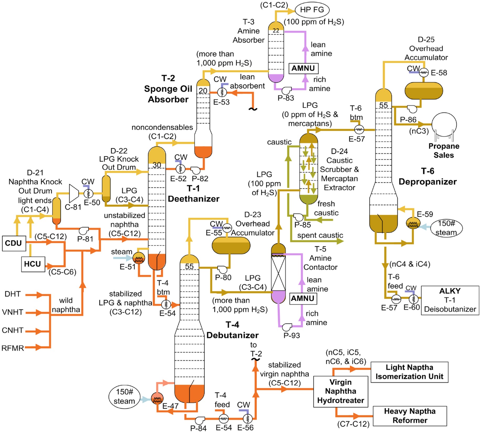
The combined compressed gas flows to the primary absorber, where C3+ components are absorbed into a circulating lean oil — typically unstabilized naphtha from the crude unit or debutanizer bottoms from within the plant itself. The absorber is equipped with intercoolers to remove the heat of absorption, which is essential to maximizing recovery: propane-plus recovery of 90–95% or better is typical. Tray or packed internals are conventional; no special metallurgy or fouling-resistant design is required in saturated service.
4. Stripper (C2 Rejection)
The rich oil from the absorber base is sent to a stripper column, where co-absorbed ethane and lighter components are rejected overhead and recycled to the absorber feed or routed to fuel gas. This step is critical to product quality: residual ethane in the recovered LPG must be minimized to meet commercial LPG vapor pressure specifications (and cracker feed quality requirements in integrated complexes).
5. Sponge Absorber
The lean gas leaving the primary absorber passes through a secondary sponge absorber, where it is contacted with a heavier circulating oil (hydrotreated heavy naphtha or kerosene-range material) to recover entrained lean oil and naphtha vapors. This prevents gasoline-range hydrocarbon losses to the fuel gas system. The resulting dry gas — methane, ethane, and hydrogen — leaves the plant to the refinery amine system for H2S removal, then to the fuel gas header, a hydrogen recovery unit (PSA/membrane), or the steam cracker.
6. Debutanizer
The rich liquid (absorbed C3+ plus naphtha carrier) is fractionated in the debutanizer:
- Overhead: mixed C3/C4 saturated LPG, routed to the treating sequence.
- Bottoms: stabilized (debutanized) naphtha with controlled Reid Vapor Pressure, routed to the naphtha hydrotreater, gasoline pool, or cracker feed depending on refinery configuration.
7. Optional LPG Splitting
Where segregated propane and butane products are required — for example, dedicated propane and butane cracker furnace feeds (which give different ethylene yields and may be cracked in segregated coils), butane supply to alkylation or isomerization, or commercial propane/butane product blending — a depropanizer or C3/C4 splitter follows the debutanizer.
8. Associated Treating Systems
The recovered saturated LPG undergoes the standard two-step treating sequence:
- Amine treating (liquid-liquid contactor with MDEA or DEA): removes H2S to <10 ppm and CO2, producing amine-treated LPG. Mercaptans are largely unaffected at this stage.
- Caustic sweetening (Merox): extracts and oxidizes mercaptans, producing sweetened LPG meeting copper strip corrosion (1a/1b) and sulfur specifications, followed by water washing and drying where petrochemical feedstock quality (cracker feed: typically <1 ppm S, low moisture) is required.
Because the LPG is fully saturated, it can proceed directly to steam cracker furnaces after sweetening — unlike cracked LPG, which requires selective hydrogenation to remove diolefins and olefin management before such use.
Product Slate and Destinations
| Stream |
Typical Destination |
| Dry gas (C1/C2/H2) |
Amine treating → fuel gas header; optionally PSA/membrane hydrogen recovery or cracker feed |
| Mixed or split C3/C4 saturated LPG |
Amine + Merox treating → commercial/refined LPG, steam cracker feed, alkylation/isomerization feed |
| Stabilized naphtha |
Naphtha hydrotreater, gasoline blending, or steam cracker feed diet |
Distinction from the Unsaturated (Cracked) Gas Plant
| Feature |
Saturated Gas Plant |
Unsaturated (FCC/Cracked) Gas Plant |
| Feed sources |
CDU/VDU, hydrotreaters, MHC, SDA, CCR |
FCC, coker, steam cracker, other conversion units |
| Olefin content |
Negligible |
High (propylene, butylenes, diolefins) |
| Primary value driver |
LPG and naphtha recovery efficiency |
Olefin recovery efficiency (P–P splitter, alkylation feed prep) |
| Compressor design |
Conventional |
Fouling-resistant (diolefin polymerization risk) |
| LPG disposition |
Direct to treating → LPG pool or cracker feed |
Olefin recovery first; residual paraffins then treated |
| Treating requirements |
Amine + Merox |
Amine + Merox, plus selective hydrogenation where olefins/diolefins must be eliminated |
Role in the Integrated Refinery–Petrochemical Complex
In a petrochemical-oriented complex, the saturated gas plant assumes strategic importance as the consolidation point for premium cracker feedstocks. The saturated LPG it recovers — fully paraffinic, sulfur-free after treating, and free of reactive contaminants — is an ideal steam cracker feed delivering high ethylene yields. Likewise, stabilized full-range naphtha from mild hydrocracking operations can be routed unsplit to the cracker, avoiding splitter capital and energy costs. By concentrating light-ends recovery from the crude distillation and hydrotreating block in a single optimized facility, the SGP maximizes liquid yield, minimizes fuel gas downgrading, and provides the feed flexibility that underpins the refinery–cracker integration philosophy.
Typical Equipment List
1. Feed Receiving and Separation
| Equipment |
Function |
| Feed knockout (KO) drum(s) |
Remove entrained liquids and water from incoming off-gas streams |
| Low-pressure suction KO drum |
Protect compressor from liquid carryover |
| High-pressure gas KO vessel |
Separate condensables from hydrotreater/MHC high-pressure off-gas |
| Liquid collection/boot drum |
Collect unstabilized naphtha from KO drum boots |
| Feed filters/coalescers |
Remove fine liquid aerosols upstream of compression |
2. Compression
| Equipment |
Function |
| Wet gas compressor(s) — multi-stage reciprocating or centrifugal |
Boost low-pressure off-gas to absorber pressure (~10–15 bar) |
| Interstage coolers (air or water) |
Remove heat of compression between stages |
| Interstage knockout drums |
Separate condensed hydrocarbons and water between stages |
| Discharge cooler |
Cool final-stage gas ahead of the absorber |
| Discharge KO drum |
Final liquid removal before absorption |
| Compressor driver (electric motor or steam turbine) |
Prime mover |
| Lube/seal oil system, surge control (antisurge valves, recycle loops) |
Compressor protection and operability |
3. Absorption and Stripping Section
| Equipment |
Function |
| Primary absorber column (trayed or packed) |
Absorb C3+ from gas into lean naphtha oil |
| Absorber intercoolers / pump-around coolers |
Remove heat of absorption; maximize C3 recovery |
| Lean oil circulation pumps |
Circulate naphtha lean oil through absorber |
| Stripper column (C2 reject / de-ethanizing function) |
Strip co-absorbed ethane and lighter from rich oil |
| Stripper reboiler (steam or hot oil) |
Supply stripping heat |
| Stripper overhead condenser and reflux drum |
Reflux and net overhead gas to absorber/fuel gas |
| Sponge (secondary) absorber column |
Recover entrained lean oil from lean gas |
| Sponge oil circulation pumps |
Circulate heavy sponge oil |
4. Debutanizer / Fractionation Section
| Equipment |
Function |
| Debutanizer feed/bottoms heat exchanger |
Feed preheat; heat recovery |
| Debutanizer feed preheater |
Final feed heating |
| Debutanizer column (trayed) |
Separate C3/C4 LPG overhead from stabilized naphtha bottoms |
| Debutanizer reboiler (steam/hot oil) |
Column heat input |
| Debutanizer overhead condenser (air/water) |
Condense LPG overhead |
| Debutanizer reflux drum |
Reflux and net LPG product separation; water boot |
| Reflux pumps |
Return reflux to column |
| LPG product rundown coolers |
Cool LPG to storage/treating conditions |
| Stabilized naphtha rundown cooler |
Cool bottoms product to storage |
| (Optional) Depropanizer or C3/C4 splitter column + reboiler, condenser, reflux system |
Split LPG into propane and butane products |
5. Heat Exchange and Utilities
| Equipment |
Function |
| Rich/lean oil heat exchangers |
Heat recovery between rich and regenerated streams |
| Air coolers (fin-fan) |
Cooling duty throughout |
| Water coolers (shell-and-tube) |
Trim cooling |
| Steam/hot oil system tie-ins |
Reboiler heat supply |
| Condensate collection drum |
Steam condensate recovery |
6. Treating Tie-Ins (adjacent, often integrated)
| Equipment |
Function |
| LPG amine contactor (liquid-liquid) + regenerator tie-in |
H2S/CO2 removal from LPG product |
| Merox extractor / fiber-film contactor + oxidizer + disulfide separator |
Mercaptan sweetening of LPG |
| Fuel gas amine absorber |
H2S removal from dry gas leaving sponge absorber |
| Water wash vessel and LPG dryer (molecular sieve) |
Final product polishing for cracker feed quality |
7. Safety, Relief and Drainage
| Equipment |
Function |
| Pressure safety valves (PSVs) on all pressure equipment |
Overpressure protection |
| Flare KO drum and flare header connections |
Safe relief disposal |
| Closed blowdown (CBD) drum |
Depressurization and drain collection |
| Oily water sewer / API separator tie-in |
Drainage management |
| Sour water collection (from KO boots) |
Route H2S/NH3-laden water to sour water stripper |
8. Instrumentation and Control
| Equipment |
Function |
| Flow/pressure/temperature/level instruments and control valves |
Process control |
| Antisurge control system |
Compressor protection |
| Online analyzers (H2S, RVP, C2-in-LPG, composition GC) |
Product quality monitoring |
| SIS (Safety Instrumented System) |
Emergency shutdown and depressurization logic |
Typical equipment count for a mid-size SGP (2–4 MMTPA crude-equivalent):
~3–4 columns, 1–2 compressor trains, 8–12 heat exchangers/coolers, 6–10 drums/vessels, 10–15 pump sets — compact relative to primary process units, but central to refinery light-ends economics.