Technology Summary
Natural gas produced from reservoirs is invariably saturated with water vapor. If left untreated, this moisture causes hydrate formation that can plug pipelines and cryogenic equipment, promotes corrosion in carbon steel infrastructure, and contaminates downstream processes such as NGL extraction and LNG liquefaction. Molecular sieve dehydration — based on the principle of Temperature Swing Adsorption (TSA) — is the standard solution wherever deep water removal is required, typically defined as achieving water content below 1 ppmv (parts per million by volume) and water dewpoints as low as −100°C (−148°F).
The process exploits the selective adsorption properties of crystalline aluminosilicate zeolites (molecular sieves), whose uniform sub-nanometre pore structure acts simultaneously as a molecular sieve — admitting water molecules while excluding most hydrocarbons — and as a highly polar adsorbent that binds water strongly via physical forces. Because the adsorbent can be thermally regenerated, industrial units cycle continuously between an adsorption phase and a regeneration phase across multiple parallel vessels, ensuring uninterrupted dry gas production.
Molecular sieve TSA is the technology of choice upstream of:
For applications requiring only pipeline-quality dryness (e.g., ≤ 7 lb H₂O/MMscf), glycol absorption (TEG) is generally more economical, and a hybrid TEG + molecular sieve arrangement is widely used to reduce the water loading — and therefore the required adsorbent volume and regeneration energy — on the molecular sieve unit.
Step-by-Step Process Description
Step 1 — Feed Gas Pre-treatment (Inlet Separation)
Wet feed gas enters an inlet knockout (KO) drum (also called the inlet feed separator) upstream of the adsorber vessels. This vessel removes free liquid water, liquid hydrocarbons, glycol, and any solids or aerosols that could contaminate or prematurely saturate the molecular sieve bed. The operating temperature of the feed is typically controlled to a safe margin above the hydrate formation temperature — usually 5°C to 10°C above — while being as cool as practical, since lower feed temperatures increase the equilibrium water uptake capacity of the sieve. If methanol is injected upstream for hydrate inhibition, the sieve type (3A vs. 4A) must account for methanol co-adsorption behavior (see Adsorbents section).
Step 2 — Adsorption (Drying)
Dry, clean feed gas at operating pressure flows downward through one or more adsorber towers loaded with molecular sieve pellets or beads. Downflow during adsorption prevents bed fluidization under abnormal flow surges. As gas passes through the bed, water molecules are selectively captured in the zeolite pore channels, and the effluent gas exits the bottom of the vessel meeting the required dewpoint specification.
Two distinct zones exist within the active adsorber bed at any moment:
- Saturation Zone (SZ): The top portion of the bed, already equilibrium-saturated with water under feed conditions.
- Mass Transfer Zone (MTZ): The active adsorption front migrating downward toward the vessel outlet. The MTZ represents the transition from wet to dry gas and its length determines how efficiently the adsorbent is utilized. A shorter MTZ — characteristic of molecular sieves compared to silica gel or alumina — enables more efficient use of the bed volume.
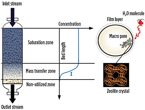
Figure 1 - Mass transfer zone in an adsorption vessel
Typical adsorption step duration: 8 hr to 24 hr (most commonly 16 hr in a 2+1 configuration). The cycle ends when the MTZ approaches the vessel outlet and breakthrough is imminent.
Key adsorption operating parameters:
| Parameter |
Typical Range |
| Operating pressure |
40–100 bara
(typical: 60–70 bara for LNG/NGL) |
| Feed gas temperature |
15–50°C (cooled to above hydrate point) |
| Superficial gas velocity (adsorption) |
0.05–0.20 m/s |
| Bed pressure drop (adsorption) |
≤ 60 kPa (end-of-run: ≤ 120 kPa) |
| Minimum pressure drop per unit length |
≥ 230 Pa/m
(to ensure radial flow distribution) |
| Adsorption cycle time |
8–24 hr |
| Vessel L/D ratio |
> 2 (to avoid "pancake reactor" geometry) |
| Typical bed height |
2–10 m |
Step 3 — Switching (Vessel Changeover)
Before breakthrough occurs, automated on-off valves (typically ball valves or plug valves rated for the full operating pressure) redirect feed gas to the next adsorber vessel already in standby (freshly regenerated and cooled). Timing of the changeover is controlled by PLC/DCS logic on a fixed or variable cycle schedule. Variable cycling — where cycle time is progressively shortened as the adsorbent ages — can extend sieve life and reduce the total number of thermal cycles.
Step 4 — Depressurization (optional) and Regeneration Gas Flow Initiation
The saturated vessel is isolated from the feed and product gas streams. Depending on the plant configuration, the vessel may remain at operating pressure (high-pressure regeneration) or be partially depressurized to reduce the energy required for heating. A slip stream of dry product gas — typically ~10% of feed flow — is drawn off as regeneration gas and routed upward (countercurrent to adsorption flow direction) through the saturated bed.
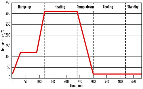
Figure 2 - Typical regeneration temperature profile
Step 5 — Heating (Regeneration — Thermal Phase)
The regeneration gas is heated in a regeneration gas heater (fired heater, steam exchanger, or electric heater) before entering the bottom of the saturated adsorber. Temperature is ramped up progressively — using a stepped or linear profile — to avoid premature desorption of water from the bed bottom before the upper portion of the bed has been preheated. If the upper bed remains cold and saturated when water desorbs from the lower bed, the desorbed water vapor can re-condense as hot liquid water on the clay binder, causing irreversible caking and structural destruction of the pellets.
The regeneration gas exits the top of the vessel laden with desorbed water vapor and at elevated temperature.
Typical regeneration thermal parameters:
| Parameter |
Typical Range |
Maximum bed regeneration temperature
(outlet gas) |
230–290°C (4A sieve);
max thermal limit: 320°C |
Regeneration inlet gas temperature
(heater outlet) |
260–320°C |
| Heating step duration |
4–8 hr |
| Regeneration gas flow rate |
~10% of feed gas flow |
| Heating ramp rate |
Controlled step profile to prevent
hot liquid water formation |
Step 6 — Water Recovery (Regeneration Gas KO Drum)
The hot, water-laden regeneration gas exiting the adsorber vessel is cooled in the regeneration gas cooler (air cooler or water-cooled exchanger). Water vapor condenses and is separated in the regeneration KO drum as produced water, which is routed to disposal or water treatment. The partially dried regeneration gas is then either:
- Recompressed and recycled to the feed inlet (closed-loop configuration — preferred to minimize gas losses), or
- Combined with the feed gas upstream of the inlet KO drum
For units treating mercaptans simultaneously, recycling the regeneration gas is not viable without first treating for sulfur species, which accumulate in a closed loop.
Step 7 — Cooling
After heating, a cooling step passes unheated dry gas (or a portion of cold product gas) upward through the regenerated bed to reduce the bed temperature back to near-ambient/operating conditions before the vessel returns to adsorption service. Cooling step duration is typically 2–4 hr. The end-of-cooling bed temperature must be sufficiently low to prevent thermal re-desorption of water from the hot sieve when feed gas is re-introduced, but not so cold as to risk re-adsorption of moisture from the cooling gas if the cooling gas is not fully dry.
Step 8 — Standby
If a 3-vessel (2+1) configuration is used and the cooling step completes before the on-stream vessel reaches end of cycle, the regenerated vessel enters a standby phase, pressurized and dry, awaiting the next adsorption cycle.
Vessel Configurations
The number of adsorber vessels and their cycle allocation is a key design variable:
| Configuration |
Vessels |
Adsorption |
Regeneration |
Notes |
| 1+1 |
2 |
1 |
1 |
Simplest; adsorption and regeneration times equal
(~16 hr each); suitable for smaller plants |
| 2+1 |
3 |
2 |
1 |
Most common for LNG/NGL;
8 hr regeneration window within 24 hr cycle |
| 3+1 |
4 |
3 |
1 |
Used for large trains
with short cycle needs |
| 3+2 or 4+2 |
5–6 |
Multiple |
Multiple |
Large-scale LNG,
very high feed rates or
multi-contaminant removal |
Adsorbents
Zeolite Types for Dehydration
Molecular sieves used in gas dehydration are crystalline aluminosilicates of the Linde Type A (LTA) framework, in which the cation type determines the effective pore aperture:
| Type |
Cation |
Pore Diameter |
Primary Application |
| 3A (KA) |
K⁺ |
~3 Å |
Pipeline gas dehydration where methanol injection is used upstream; methanol passes through the 3A pore and can be recovered downstream |
| 4A (NaA) |
Na⁺ |
~4 Å |
LNG and NGL plant dehydration; higher water uptake capacity and thermal stability than 3A; preferred when no methanol is present |
| 5A (CaA) |
Ca²⁺ |
~5 Å |
Dehydration with simultaneous removal of CO₂, H₂S, and some mercaptans; higher co-adsorption risk |
| 13X (NaX) |
Na⁺ |
~10 Å |
Multi-contaminant removal (H₂O, CO₂, mercaptans); co-adsorption of heavier hydrocarbons is a known concern |
For LNG applications, Type 4A is the industry standard: it offers the best combination of water uptake capacity, thermal stability (limit: 320°C), and minimal co-adsorption of methane and heavier hydrocarbons. For pipeline gas applications where methanol is injected as hydrate inhibitor upstream, 3A is typically specified because the narrower pore excludes methanol, allowing it to pass through unretained and be recovered downstream in NGL fractionation.
Physical Forms
Molecular sieves are marketed as:
- Cylindrical pellets (extrudates): 1/16 in. (1.6 mm) and 1/8 in. (3.2 mm) diameter — standard for gas service
- Beads (spheres): 2–5 mm diameter — lower pressure drop, used in high-flow or bottom-of-bed layers
- Beds are typically layered to optimize pressure drop and mass transfer: coarser particles (1/8 in.) in the upper bed layers to minimize ΔP, finer particles (1/16 in.) in the lower layers for a shorter MTZ and better effluent quality
Physical Properties of Molecular Sieve 4A
| Property |
Value |
| Bulk density |
640–720 kg/m³ |
| Surface area |
600–800 m²/g |
| Pore volume |
~0.28 cm³/g |
| Specific heat |
~1.00 kJ/kg·K |
| Minimum effluent moisture content |
< 0.1 ppmv H₂O |
| Minimum dewpoint achievable |
−100°C (−150°F) |
| Regeneration temperature range |
200–315°C |
| Maximum operating temperature |
320°C (thermal stability limit) |
| Equilibrium water capacity (fresh, 25°C) |
~20–22 wt% |
| Equilibrium water capacity (end-of-run) |
~10–12 wt% (design basis) |
Comparison vs. Other Solid Desiccants
| Desiccant |
Minimum dewpoint |
Regeneration temp. |
Water capacity |
Key
limitation |
| Silica gel |
−60°C |
~190°C |
High |
Cannot reach
< 5 ppmv |
| Activated alumina |
−75°C |
160–220°C |
Moderate |
Cannot reach
< 10 ppmv |
| Molecular sieve (4A) |
−100°C |
200–315°C |
Moderate |
Higher regen. energy; strict regen. protocol required |
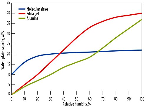
Figure 3 - Typical isotherms of some adsorbents
Specialty / Proprietary Adsorbents
| Product |
Supplier |
Capability |
| Sorbead® R / WS |
BASF |
Silica gel–alumina hybrid for simultaneous
H₂O + heavy HHC removal;
used in Quick-Cycle process |
| AxSorb® 541 / 543 |
Axens (CECA) |
Simultaneous H₂O + CO₂ / H₂S removal
for LNG applications |
| UOP MOLSIV™ 4A |
Honeywell UOP |
Proprietary zeolite formulations;
specified in majority of LNG train designs (>2,400 units worldwide) |
| Zeochem Z4-01 / Z3-03 |
Zeochem |
Standard and high-density variants
for gas dehydration |
| Grace Molecular Sieve |
W.R. Grace |
3A, 4A formulations
with proprietary binder systems |
Adsorbent Lifetime and Deactivation
Fresh molecular sieve equilibrium water capacity is typically ~20–22 wt% at 25°C. This capacity declines with each regeneration cycle due to:
- thermal degradation of zeolite crystallinity
- binder dissolution from hot liquid water contact during poorly designed regeneration profiles
- coke deposition from cracking of heavy hydrocarbons at high regeneration temperatures; and
- contamination from liquid carryover upstream.
End-of-run (EOR) capacity — used as the design basis — is typically ~50–60% of fresh capacity (10–12 wt%). Typical sieve service life before changeout is 3–5 years, aligned with plant major turnaround intervals (every 4 years for most LNG trains).
Equipment List
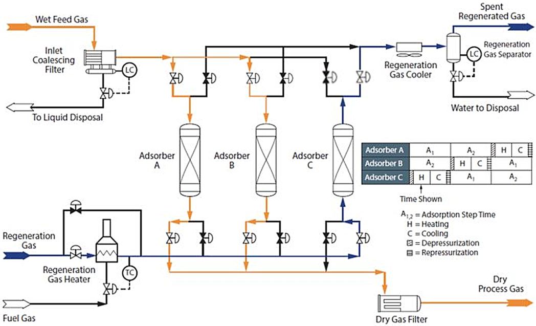
Figure 4 - Molecular Sieve Dehydration (2+1 configuration) process flow diagram
A standard molecular sieve dehydration unit comprises the following major equipment items:
Vessels and Internals
- Inlet feed KO drum / feed separator (vertical or horizontal, with mist eliminator pad or cyclone internals)
- Adsorber vessels (2 to 6 vessels depending on configuration; high-pressure, typically ASME/PED rated; internal or external insulation; internal flow distributor/collector assemblies; ceramic ball support layers above and below the sieve bed; SS screen retainer baskets)
- Regeneration gas KO drum (separates condensed water from regeneration gas effluent)
Heat Exchange and Heating
- Regeneration gas heater (options: direct-fired heater, steam-heated shell-and-tube exchanger, electric heater, or waste heat exchanger using turbine exhaust)
- Regeneration gas cooler (air-cooled heat exchanger or water-cooled shell-and-tube)
- Feed gas cooler (optional, upstream; reduces feed temperature to increase sieve capacity and minimize bed size)
Valves and Piping
- Automated switching valves (typically large-bore full-port ball valves with actuators; failure-mode design critical for safety); typically 4 switching valves per adsorber vessel (inlet, outlet, regen inlet, regen outlet)
- Pressure control valves on regeneration loop
- Check valves on product gas outlet
Instrumentation and Control
- Bed temperature profile thermowells (multiple points per vessel to monitor heating/cooling front progress)
- Pressure differential transmitters (ΔP across each bed — key for monitoring pressure drop increase as adsorbent ages or dusts)
- Moisture analyzer(s) on product gas outlet (chilled mirror hygrometer or electrolytic moisture analyzer; provides early warning of breakthrough)
- PLC/DCS cycle timer logic for automated vessel switching
Ancillary
- Feed gas inlet filter-separator (coalescing or vane-type; final protection against liquid carryover)
- Sieve dump and load ports (manways at top and bottom of each vessel for sieve loading/unloading)
- Product gas filter (downstream of adsorbers; captures sieve dust/fines before they enter downstream equipment)
- Regeneration gas compressor (if closed-loop regeneration gas recycle is used; small recip or centrifugal compressor to overcome loop ΔP)
Process Performance
Water Removal Efficiency
Molecular sieve TSA units achieve product gas water content specifications that no other commercially mature technology can match in continuous operation:
| Performance Metric |
Typical Value |
| Product gas H₂O content |
< 0.1 ppmv (1 ppmv easily achievable;
0.1 ppmv achievable in good design) |
| Product water dewpoint |
−80°C to −100°C (−112°F to −148°F) |
| Minimum achievable dewpoint |
−100°C (−150°F) with fresh 4A sieve |
| Water removal selectivity |
Essentially complete; water is
the most strongly adsorbed species |
Co-removal Capability
Depending on the sieve type and cycle design, TSA units can achieve simultaneous removal of:
| Contaminant |
Sieve Type |
Remarks |
| Mercaptans (RSH) |
13X, 5A |
Used in NGL/LPG treating
ahead of cryogenic units |
| CO₂ |
13X, AxSorb® 541 |
Only practical at very low
CO₂ concentrations (< 50 ppmv);
for LNG where residual CO₂ must
be < 50 ppmv to prevent freezing |
| H₂S |
13X |
Limited; not a substitute for
dedicated gas sweetening upstream |
| Methanol |
4A, 13X |
Adsorbed and released
during regeneration |
| Heavy hydrocarbons (C₆+) |
Sorbead® WS, BASF |
Sorbead Quick-Cycle process
specifically designed for this |
Adsorbent Selectivity
Molecular sieves exhibit near-perfect selectivity for water over methane and lighter hydrocarbons due to the combination of pore sieving (water molecule diameter ~2.6 Å fits comfortably in 3A, 4A, 5A pores; methane at ~3.8 Å is partially excluded from 3A) and the strongly polar internal environment preferentially attracting the polar water molecule.
The flat adsorption isotherm characteristic of molecular sieves — in contrast to the steeply declining isotherms of silica gel and alumina — means that equilibrium capacity is nearly constant over a wide range of water partial pressures, enabling deep dewpoint specifications to be maintained even with dilute water inlet concentrations.
Cycle Efficiency
- Regeneration gas consumption: ~8–12% of feed gas flow (represents a product loss or recirculation load)
- Regeneration energy demand: ~2.5–4.0 GJ/tonne H₂O removed (significantly higher than TEG dehydration at ~0.5–1.0 GJ/tonne H₂O)
- Hybrid TEG + molecular sieve arrangements reduce regeneration energy consumption by approximately 60% compared to molecular sieve alone handling the full inlet water load
Process Economics
Capital Cost (CAPEX)
Molecular sieve dehydration units are capital-intensive compared to glycol systems, primarily due to the high-pressure vessel construction, automated valve systems, and regeneration heating infrastructure. Key cost drivers include:
- Operating pressure: CAPEX passes through a minimum at approximately 25–30 bara; both lower pressure (larger vessel diameters) and very high pressure (thicker vessel walls) increase costs
- Number of vessels: A 2+1 (three-vessel) configuration typically costs 30–40% more than a 1+1 (two-vessel) configuration but significantly reduces adsorbent volume and allows shorter cycle times
- Feed water loading: A TEG pre-dehydration step upstream reduces feed water loading, approximately halving the number of required adsorber vessels for the same duty
- Adsorbent replacement: Sieve changeout every 3–5 years is a significant planned maintenance cost; high-density sieve variants reduce the required sieve mass and lower changeout cost
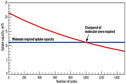
Figure 5 - Typical deactivation and molecular sieve changeout profile
Operating Cost (OPEX)
| OPEX Element |
Remarks |
| Regeneration energy (fuel gas or steam) |
Dominant OPEX item; ~2.5–4.0 GJ/tonne H₂O removed |
| Regeneration gas product loss |
~8–12% of feed flow diverted; closed-loop recycle recovers most of this |
| Adsorbent replacement |
Every 3–5 years; sieve cost: ~USD 2,000–5,000/tonne depending on type |
| Pressure drop energy penalty |
ΔP across beds = compression energy loss; significant in high-pressure LNG applications |
| Instrument maintenance |
Moisture analyzers, switching valves, thermowells require regular calibration and maintenance |
The IEA GHG study comparing dehydration technologies concluded that TEG systems have significantly lower OPEX (energy per kg water removed) than molecular sieve for bulk dehydration, confirming that molecular sieve should be used only where deep dewpoints are required — or in combination with TEG for bulk pre-removal.
Global Deployments
Molecular sieve dehydration is ubiquitous in the global gas processing industry. Key deployment contexts include:
LNG Liquefaction Plants
Molecular sieve dehydration is a universal element of every LNG liquefaction train worldwide, where the water specification is ≤ 0.1 ppmv to prevent ice formation in cryogenic heat exchangers and plate-fin exchangers (PFHE). Honeywell UOP reports that its molecular sieve products have been specified in over 2,400 natural gas processing and LNG units worldwide. Major LNG plants with molecular sieve DHU installations include:
- Qatar — QatarEnergy LNG trains (world's largest LNG complex; 77 MTPA capacity): all 14 LNG trains equipped with molecular sieve DHUs upstream of the APCI C3-MR liquefaction exchangers
- Australia — Gorgon LNG, Wheatstone LNG, Australia Pacific LNG, Ichthys LNG, QCLNG, GLNG: all equipped with molecular sieve dehydration
- USA — Sabine Pass LNG, Corpus Christi LNG, Freeport LNG, Cameron LNG, Cove Point LNG: all Train 1–N configurations include TSA molecular sieve DHUs
- Russia — Sakhalin-2 LNG (Sakhalinskaya Energija), Yamal LNG (Novatek): both equipped with molecular sieve dehydration
- Malaysia — MLNG Satu/Dua/Tiga and Train 9 (Bintulu LNG complex, operated by Petronas)
- Nigeria — Nigenria LNG Limited (NLNG) Trains 1–7 (Bonny Island)
NGL/Gas Processing Plants
Every cryogenic NGL extraction plant (turboexpander-based) operating at temperatures below −40°C requires molecular sieve dehydration upstream to prevent hydrate and ice formation in the cold box and demethanizer. This encompasses thousands of gas processing plants in:
- USA (Permian Basin, Midcontinent, Rockies, Gulf Coast)
- Middle East (Saudi Aramco gas plants, ADNOC, KPC)
- North Sea (UKCS, Norwegian Continental Shelf)
- Canada (Alberta gas processing corridor)
- China (CNOOC, PetroChina, Sinopec gas fields)
Pipeline Gas Export
While TEG dehydration is more common for pipeline specifications (≤ 7 lb H₂O/MMscf in North America; ≤ 50–80 mg/Nm³ in Europe), molecular sieve or hybrid TEG + mol sieve systems are applied where:
- Sub-zero ambient conditions require deeper dewpoints to prevent condensation in buried pipelines
- Sour gas is present (glycol systems require more complex design for sour service)
- Remote/offshore locations favor lower-maintenance solid desiccant systems
CCS / CCUS Applications
BASF's Sorbead® technology has been qualified by Shell for CO₂ drying in CCS applications, representing an emerging deployment context beyond traditional hydrocarbon gas processing.
References
- John M. Campbell & Co. — Malino H. (May 2005). Benefits of Standby Time in Adsorption Dehydration Process
- Gas Processing News — Herold R.H.M. & Mokhatab S. (Aug 1, 2017). Optimal Design and Operation of Molecular Sieve Gas Dehydration Units — Part 1.
- Gas Processing News — Jain S. (Feb 1, 2018). Proper Regeneration of Molecular Sieves in TSA Processes — Part 1
- Gulf Professional Publishing — Mokhatab S., & Poe W.A. (2012). Handbook of Natural Gas Transmission and Processing, 2nd Ed., Waltham, Massachusetts
- KLM Technology Group — Kolmetz K. & Lestari A.Z. (Rev 01 Sep 2015). Mole Sieve Dehydration: Selection, Sizing and Troubleshooting. Kolmetz Handbook of Process Equipment Design (Engineering Design Guidelines)
- IEAGHG — Technical Report 2014-04 ( (Apr 1, 2014): Evaluation and Analysis of the Performance of Dehydration Technologies for CCS
- BASF — News Release (Sep 29, 2021): Shell Qualifies BASF Sorbead® Adsorption Technology for Carbon Capture and Storage
- BASF — Sorbead® for Natural Gas (Accessed Mar 31, 2026)
- Axens — Drying Series Adsorbents (Accessed Mar 31, 2026)
- Axens — Gas Dehydration & Purification (Accessed Mar 31, 2026)
- Honeywell UOP — Technology Bulletin UOP8459 (Sep 2019): Liquefied Natural Gas Solutions
- SPEC Oil & Gas Technologies — Molecular Sieve Dehydration (Accessed Mar 31, 2026)
- FB Group — Molecular sieve dehydration explained (Accessed Mar 31, 2026)
- Shell Global Solutions — De Bruijn J.N.H. et al. Maximizing Molecular Sieve Performance in Natural Gas Processing. GPA Annual Convention, Dallas, Texas (Mar 11–13, 2002)
- CECA SA — Terrigeol A. Molecular Sieves Contaminants: Effects, Consequences and Mitigation. GPA Europe Annual Conference, Berlin, Germany (May 23–25, 2012)
- FRAMES — Olijhoek et al. Paper GMC15 - 161: CAPEX and OPEX Considerations for Gas Dehydration Technologies, Gasmexico Congress & Exhibition (2015)