Process Overview
UOP HgSIV™ Regenerable Mercury Removal is a proprietary Honeywell UOP licensed technology in which silver-impregnated molecular sieve (HgSIV™) adsorbent is loaded into an existing TSA (Temperature Swing Adsorption) molecular sieve dehydrator. Dehydration and mercury removal are performed simultaneously in the same vessels. Mercury is adsorbed during the online (drying) step and thermally desorbed during the normal regeneration cycle, so the sorbent is continuously refreshed each cycle. The technology can be applied to both gas and liquid hydrocarbon streams.
HgSIV™ Placement Within the Gas Plant
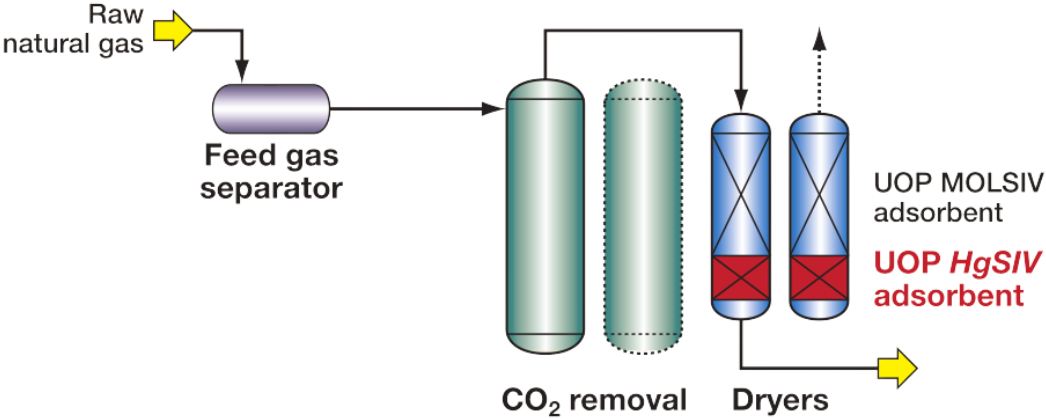
HgSIV™ adsorbent is loaded directly into existing molecular sieve dehydrator vessels. Three placement configurations are recognised:
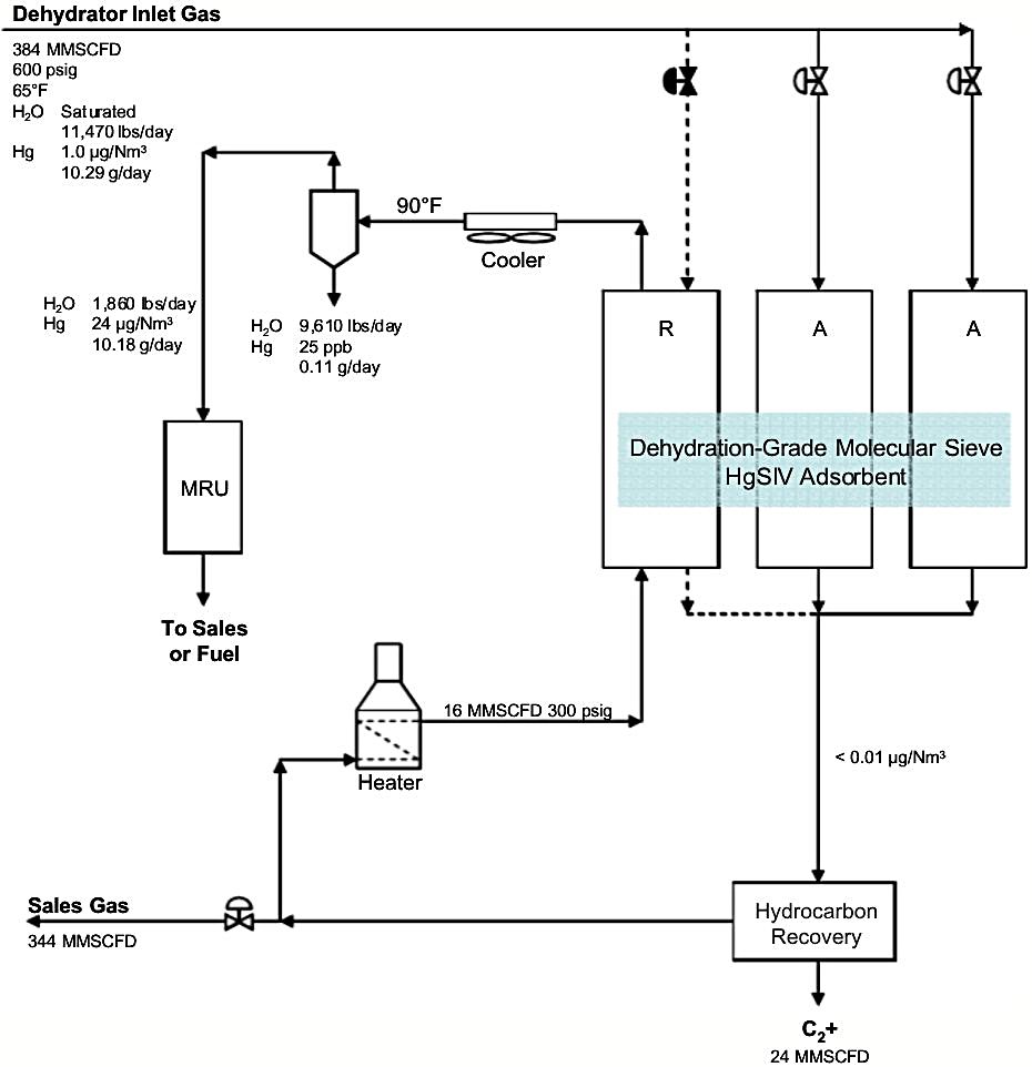
- Inside the dryers — HgSIV™ replaces a portion of the dehydration sieve in the existing vessels; no new vessels or piping required; no additional pressure drop; the dehydrator diverts all mercury and some water around the cold box; mercury exits with the spent regeneration gas to fuel gas or sales gas
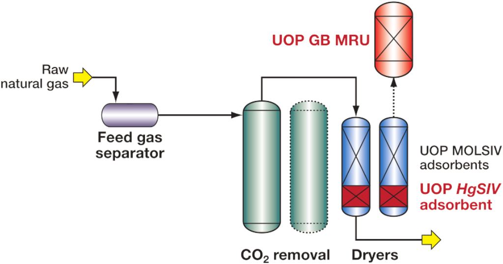
- Inside the dryers + regeneration gas treatment — HgSIV™ in the dehydrators combined with a small downstream non-regenerable GB guard bed on the spent regeneration gas loop; only a small bed is required since the regen gas volume is much smaller than the feed gas, and mercury need only be reduced to feed gas concentration rather than product specification
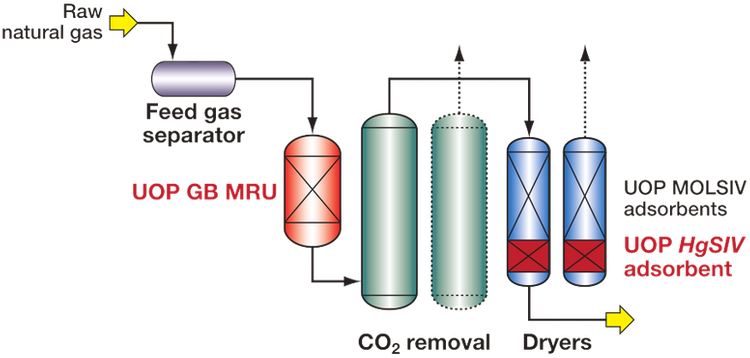
- Inside the dryers + upstream GB MRU (combined) — HgSIV™ in the dehydrators used alongside a non-regenerable GB unit at the plant inlet; the HgSIV™ inventory can be reduced to account for the lower mercury level entering the dehydrator; provides maximum plant protection and allows the inlet MRU to be operated past breakthrough without risk to the cold box
Step-by-Step Process Description
Step 1 — Feed Gas Entry (shared with dehydration unit)
- Wet feed gas (containing both water vapour and mercury) enters the molecular sieve dehydration unit, passing first through the existing feed gas separator
- Typical operating conditions: 70°F (21°C), 845 psig (~58 barg), water-saturated feed
- No dedicated inlet separation stage is added beyond what exists in the standard dehydration unit feed system
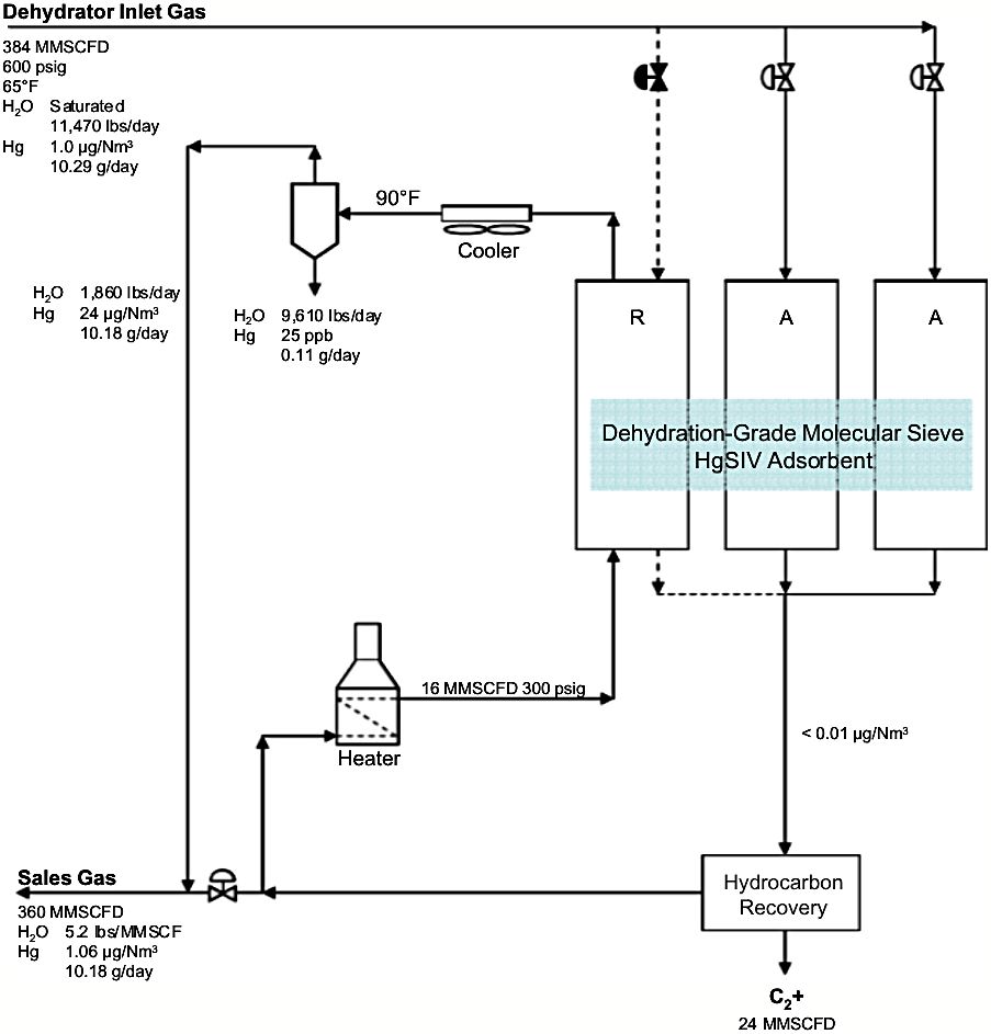
Step 2 — Simultaneous Adsorption of Water and Mercury (Online Vessel)
- Gas passes downward through the adsorber vessel loaded with a blend of:
- Standard 4A molecular sieve (MOLSIV™) for water adsorption
- HgSIV™ adsorbent for mercury adsorption
- HgSIV™ is a molecular sieve product with silver on the outer surface of the pellet or bead, where it is readily available to form an amalgam with mercury, providing a rapid rate of mercury removal:
- Hg⁰ + Ag → Ag/Hg amalgam (at adsorption temperature)
- HgSIV™ is loaded as a partial replacement of standard dehydration sieve — the bed size does not need to be increased, because mercury sorption sites are separate from and additive to water sorption sites
- HgSIV™ adsorbent is positioned at the bottom of the bed (the heating inlet end), where it is the first layer to be heated during regeneration — ensuring complete mercury desorption early in the heating cycle
- Available in beaded and pelletised forms; loaded identically to conventional molecular sieves — no nitrogen blanketing required during installation or unloading
- Adsorption cycle follows the standard TSA dehydration cycle of the host dryer (specific cycle duration not stated in source documents)
- Outlet mercury target: ≤ 0.01 µg/Nm³ (< 1 ppt by volume)
Step 3 — Thermal Regeneration (Offline Vessel)
- When the online vessel switches offline, hot dry regeneration gas — typically a small slip stream of plant residue gas — is passed upward through the bed
- The mercury desorption profile is similar to the water regeneration profile, except that mercury is completely removed from the HgSIV™ adsorbent well before the full regeneration temperature for water removal is reached
- Regeneration uses conventional TSA dryer regeneration temperatures — the same heating programme as standard molecular sieve dehydration; no special temperature modifications to the existing regeneration cycle are required
- Because mercury removal sites are regenerated each cycle with a clean gas stream, the sorbent is refreshed each cycle and retains a high and stable rate of mercury removal over the full sieve life
Step 4 — Spent Regeneration Gas Handling
The spent regeneration gas carries desorbed mercury vapour leaving the offline vessel. Four handling configurations are available, all specific to HgSIV™ in-dryer operation:
-
Option B-1 — Direct dilution to sales gas or fuel gas (no treatment)
Spent regen gas is cooled in a knockout drum, where bulk water is condensed and removed; the remaining gas (containing mercury at ~39 µg/Nm³ average for a 2.5 µg/Nm³ feed case) is routed to the fuel gas header or blended into the sales gas line; at these dilution ratios, mercury concentration in the blended stream approaches feed gas inlet levels; this is the most common choice in practice — as of the date of available references, no operating plants had opted for regen gas treatment
-
Option B-2 — GB guard bed on regen gas (treatment before recycle)
Spent regen gas (after cooling and KO separator) is routed through a small non-regenerable GB adsorbent bed; only a small bed is required since regen gas volume is much smaller than feed gas volume and mercury need only be reduced to feed gas concentration rather than product specification — allowing the bed to be loaded to higher breakthrough before replacement; treated regen gas is then recycled to feed or sales gas without mercury concern
-
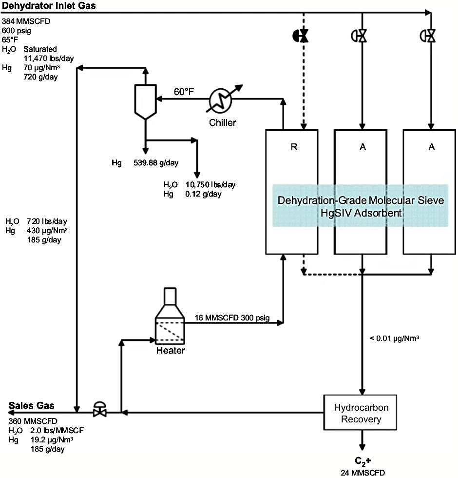
Option B-3 — Liquid mercury recovery by condensation (high Hg feeds)
At high feed mercury levels, mercury in the regen gas reaches saturation in the KO drum (~1,100 µg/Nm³ at drum conditions) and condenses as liquid metallic mercury; liquid mercury accumulates at the bottom of the separator and is decanted and recovered as a saleable product; approximately 74% of inlet mercury can be recovered as liquid in a high-mercury case (70 µg/Nm³ feed); less than 0.5% of inlet mercury reports to the condensed water phase (mercury solubility in oxygen-free water ~25 ppbw)
-
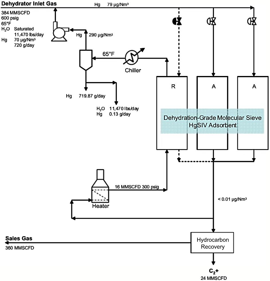
Option B-4 — Closed-cycle regeneration with product gas recycle
The dehydrator is regenerated using a closed recycle loop with product gas; the regen gas separator operates at dehydrator pressure; uncondensed mercury is returned to the dehydrator feed line, raising the dehydrator inlet mercury slightly but recovering essentially all mercury as liquid in the separator; this configuration requires a recycle compressor and good cooling but achieves complete mercury containment within the process — no mercury enters the sales gas or fuel system
Step 5 — Cooling and Re-pressurisation
- After regeneration, the vessel is cooled with cool dry gas before switching back online
- Standard TSA switching sequence: adsorption → heating → cooling → standby/online
Step 6 — Outlet Filtration
- Product gas exits through outlet particle filters (2×100%)
- Outlet mercury specification confirmed: ≤ 0.01 µg/Nm³
Equipment List
| Item |
Type / Specification |
Molecular sieve adsorber vessels
(×2 or ×3) |
Existing TSA dehydrator vessels; HgSIV™ loaded as partial bed replacement; no resizing required |
| HgSIV™ adsorbent |
Silver on outer surface of molecular sieve pellet/bead; beaded or pelletised; UOP proprietary |
Standard MOLSIV™
4A sieve |
Water adsorption layer; retained alongside HgSIV™ |
| Regeneration gas heater |
Electric or fired; heats regen gas to standard TSA temperature |
| Spent regen gas cooler / KO drum |
Cools regen gas; condenses water; condensed liquid Hg recovery at high Hg feeds |
GB guard bed
(Option B-2 only) |
Small non-regenerable GB adsorbent vessel on regen gas loop |
Regen gas chiller
(Options B-3 and B-4) |
Cools spent regen gas below mercury dew point to condense liquid mercury in the KO separator; chiller required in addition to standard cooler |
Regen gas recycle compressor
(Option B-4 only) |
Returns uncondensed separator gas to dehydrator feed line in closed-cycle regeneration configuration |
| TSA cycle controller |
UOP-designed switching / sequence controller (licensed) |
| Outlet particle filters |
2×100% |
| Mercury analyser |
On product gas outlet; CVAFS type recommended for field measurement to 0.01 µg/Nm³ |
Mercury Material Balance — Reference Case
For a 545 MMSCFD plant, feed at 70°F / 845 psig, feed Hg = 2.5 µg/Nm³:
| Stream |
Mercury Load |
| Feed gas total Hg |
34.6 g/day |
| Product dry gas (Hg-free) |
< 0.01 µg/Nm³ |
| Condensed water from KO drum |
< 0.5% of inlet (< 0.154 g/day) |
| Regen gas to fuel/sales (Option A) |
~34.45 g/day at avg. 39.4 µg/Nm³ |
| Regen gas volume |
34.4 MMSCFD (6.3% of feed) |
Performance & Efficiency
- Outlet mercury: ≤ 0.01 µg/Nm³ routinely achieved — equal to or better than non-regenerable systems
- Silver sites remain active over full sieve life (3–5 years, same as standard dehydration sieve lifetime); no periodic sorbent change-out for mercury loading
- The service life of HgSIV™ adsorbent often exceeds that of the dehydration grade molecular sieve and can be reused after the standard sieve is replaced — further reducing lifecycle cost
- Bed size unchanged vs. standard dehydration design; no additional pressure drop vs. a standalone dehydration unit
- Effective primarily for elemental mercury (dominant form in natural gas); some ionic and organic forms may also be captured
- Spent HgSIV™, when properly regenerated prior to unloading, passes the EPA TCLP test and qualifies as non-hazardous waste for disposal — a significant advantage over non-regenerable sorbents
Economics
- No additional adsorption vessels required vs. a plant already designed with a TSA dehydrator — major CAPEX saving
- OPEX components:
- Regeneration gas fuel (shared with dehydration, no incremental cost)
- Optional: GB guard bed sorbent replacement (small volume, infrequent)
- Optional: liquid mercury handling/sales at high Hg feed cases
- Sorbent cost: HgSIV™ replaces only a portion of standard molecular sieve; incremental sorbent cost vs. standard dehydration is modest
- Honeywell UOP process license fee and proprietary sorbent supply apply
- Most cost-effective for new LNG or cryogenic NGL plants where a TSA dehydrator is already in the design basis; retrofit to existing dehydrators is also feasible as a drop-in with no civil or mechanical modifications
- Eliminates spent hazardous sorbent disposal costs associated with non-regenerable systems
Deployments
At the time of the earlier referenced UOP technical paper (Corvini et al., 2002), HgSIV™ had been installed in over 25 gas dryers and 7 liquid dryers globally, with installations in the Far East, Middle East, Africa, South America, and the United States. A subsequent UOP publication (Markovs & Clark, 2005) confirmed over 30 units in gas and liquid service across LNG plants, cryogenic hydrocarbon recovery plants, and petrochemical plants.
Reference plant — PTT GSP-5, Thailand (gas phase):
- Feed rate: 265 MMSCFD per vessel; pressure: 48 kg/cm²; temperature: 18°C
- Feed Hg: 300 µg/Nm³; outlet Hg: < 0.01 µg/Nm³ from start-up
- Design bed life: 4 years; replaced sulphur-impregnated carbon predecessor
Reference plant — PTT GSP-4, Thailand (liquid phase):
- Feed: natural gas condensate; flow rate: 6,962 kg/h; pressure: 31 barg; temperature: 12°C
- Feed Hg: 2,000 ppbw; outlet Hg: < 1 ppbw; also removing H₂S and AsH₃
The technology is the preferred choice for LNG pretreatment trains in SE Asia and the Middle East, where both elevated mercury levels and brazed aluminium cryogenic heat exchangers are present.
References
- Corvini, G., Stiltner J. & Clark K. (Feb 1, 2002). Mercury Removal from Natural Gas and Liquid Streams
- Markovs J., & Clark K. (2005). Optimized mercury removal in gas plants. Paper presented at the GPA 84th Annual Convention, San Antonio, TX, USA, March 13–16, 2005
- Eckersley N., UOP LLC (May 9, 2013). Advanced Mercury Removal Technologies. Paper presented at GPAC 2013, Calgary, AB, Canada
- Mishra S., UOP (Q1, 2014). Mercury treatment options for natural gas plants. PTQ
- UOP. UOP Mercury Removal for Natural Gas Production Brochure (Document version: Mar 5, 2020)