A detailed description of the Bayer Process is provided at the 'Technology Type' level.
Process Steps, Conditions & Parameters (PFD-Based)
Figure 1 — Bayer Process Block Flow Diagram | Source: Environmental Protection Agency (EPA) of Ireland (Apr 2019)
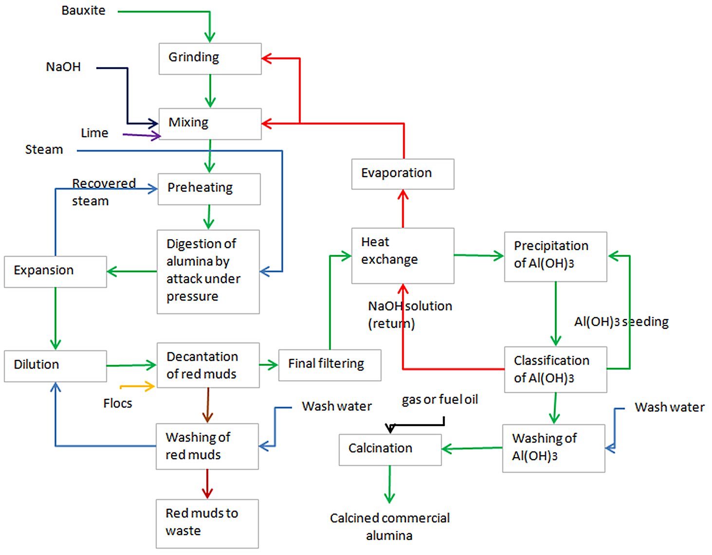
The Bayer process follows a continuous loop of six principal stages:
Step 1 — Ore Preparation (Crushing & Grinding)
Bauxite is crushed at the mine and conveyed to the refinery, where it is ground in SAG (semi-autogenous) and/or ball mills to a particle size of ≤1.5 mm. Hot recycled caustic liquor is added during milling to produce a pumpable slurry (~40–55% solids). The slurry is transferred to holding/slurry storage tanks to buffer supply interruptions and begin desilication — the early precipitation of reactive silica as sodium aluminium silicate before the main digestion circuit.
| Parameter |
Value |
| Target particle size |
≤1.5 mm |
| Slurry solids concentration |
~40–55 wt% |
| NaOH addition |
From recycled spent liquor |
Step 2 — Digestion
The bauxite slurry is pumped through preheaters and into pressurised autoclave digesters, where additional concentrated NaOH is added. Temperature and pressure depend on bauxite mineralogy:
| Mineral Phase |
Temperature |
Pressure |
| Gibbsite |
135–150°C |
Near-atmospheric |
| Boehmite |
205–245°C |
Elevated (~1.5–3.5 MPa) |
| Diaspore |
>250°C |
~3.5 MPa (~35 atm) |
The alumina dissolves selectively to form sodium tetrahydroxoaluminate (green liquor/pregnant liquor), while iron oxides, titanium oxide and calcium compounds remain undissolved. Lime (CaO) may be added to precipitate silica as calcium silicate, protecting yield. Residence time in digesters is typically 30–60 minutes.
Step 3 — Clarification (Solid–Liquid Separation)
The hot slurry is cooled and transferred through flash tanks (which recover steam/heat) to large gravity settling thickeners (mud thickeners). The undissolved solids — red mud (predominantly iron oxide, silica, titania, unreacted alumina) — settle and are separated from the clarified pregnant liquor. Flocculants such as starch are added to improve settling of fine particles. The pregnant liquor is polished through security filters (leaf or pressure filters) to eliminate fine solids before precipitation.
The red mud underflow is washed in a counter-current decantation (CCD) washing train to recover caustic soda, which is recycled. Washed residue is pumped to residue disposal areas (RDA).
| Parameter |
Value |
| Thickener diameter |
Up to 60 m+ |
| Flocculant |
Starch or synthetic polymer |
| Red mud generation |
~1.0–2.0 t dry/t alumina (varies by bauxite) |
| Caustic recovery |
>95% by CCD washing |
Step 4 — Precipitation (Crystallisation)
The clarified pregnant liquor (supersaturated in NaAlO2) is cooled progressively through plate heat exchangers, transferring heat to the cold spent liquor return stream. The cooled liquor is seeded with fine Al(OH)3 crystals from previous cycles in large precipitation tanks (precipitators) operating in series. Crystals nucleate on the seeds, grow and agglomerate over a residence time of 24–72 hours. The slurry is then classified:
-
Coarse fraction (product hydrate) → calcination
-
Fine fraction (seed crystals) → recycled back to precipitation tank feed
-
Spent liquor → evaporation and return to digestion
| Parameter |
Value |
| Precipitation temperature |
55–75°C (decreasing through chain) |
| Seed ratio |
300–600 g seed/L liquor |
| Residence time |
24–72 hours |
| Al(OH)3 recovery |
~90% of dissolved alumina |
| Precipitator tank volume |
Up to 10,000 m³ each |
Step 5 — Evaporation (Liquor Reconcentration)
Spent liquor from precipitation is dilute in NaOH and must be reconcentrated before returning to digestion. This is achieved in multi-effect evaporator trains using steam heat. Evaporation also concentrates organic impurities (primarily sodium oxalate) that build up in the circuit; these are managed by oxalate seeding and precipitation or liquor burning in a rotary kiln.
Step 6 — Calcination
Washed and filtered Al(OH)3 hydrate is fed into high-temperature calciners to drive off chemically bound water and produce anhydrous α-Al2O3:
- At 400–600°C: γ-Al2O3 forms (chemically active)
- At 1,000°C (typical SGA production): transition aluminas
- Above 1,150°C: α-Al2O3 (corundum — inert ceramic grade)
Smelter-grade alumina (SGA) is produced at approximately 1,000°C. The final product is a white crystalline powder with particle size 0.5–10 μm and Na2O content of 300–7,000 ppm.
| Parameter |
Value |
| Calcination temperature (SGA) |
950–1,050°C |
| Equipment |
Rotary kilns or CFB flash calciners |
| Calcination energy |
~1.4 GJ/t alumina (theoretical) |
| Product phase |
α-Al2O3 (SGA) |
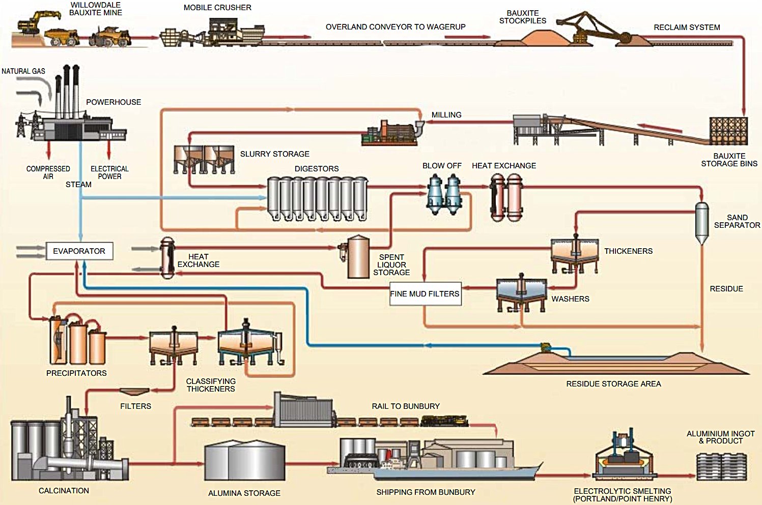
Key Equipment & Devices
Figure 2 — Bayer Process Flow Diagram - Wagerup refinery expansion | Source: Alcoa (Aug 2003)
| Equipment |
Function |
Key Specifications |
| SAG/Ball Mills |
Bauxite grinding to slurry |
Particle size target ≤1.5 mm |
| Slurry Storage Tanks |
Buffer storage & pre-desilication |
Agitated; lined steel vessels |
| Preheaters (Shell & Tube HX) |
Slurry preheat before digester |
Steam heated; recovers flash steam |
| Digesters / Autoclaves |
High-T/P dissolution of alumina |
135–250°C, up to 35 atm; series-connected |
| Flash Tanks |
Pressure let-down + heat recovery |
Multi-stage; steam recovered to preheaters |
| Rotary Sand Trap |
Remove coarse undissolved solids |
Before thickeners |
| Mud Thickeners (Settlers) |
Red mud gravity settling |
Rake thickeners, diameter up to 60 m+ |
| CCD Washing Train |
Caustic recovery from red mud |
Counter-current decantation; multiple stages |
| Security/Leaf Filters |
Final polishing of pregnant liquor |
Pressure leaf or vacuum drum filters |
| Plate Heat Exchangers |
Cool pregnant liquor before precipitation |
Transfers heat to spent liquor return |
| Precipitator Tanks |
Al(OH)3 crystallisation |
Up to 10,000 m³ each; 8–20 tanks in series |
| Classifying Thickeners |
Separate seed from product hydrate |
Gravity settling; conical bottom |
| Hydrate Filters |
Dewater Al(OH)3 before calcination |
Vacuum or pressure drum filters |
| Multi-Effect Evaporators |
Reconcentrate spent caustic liquor |
Steam-driven; 3–7 effects |
| Rotary Kilns / CFB Calciners |
Calcine Al(OH)3 to Al2O3 |
950–1050°C; gas-fired |
| Electrostatic Precipitators (ESP) |
Capture alumina dust from calciners |
On each calciner stack |
| Boilers / Steam System |
Generate process steam |
High-pressure and low-pressure steam mains |
| Oxalate Kilns |
Destroy organic impurities |
Rotary kiln; oxalate → carbonate |
References
- International Aluminium Institute. The Aluminium Story > Mining and Refining > Refining Process (Feb 15, 2022)
- IDC Technologies. Bayer Process (Document date Nov 18, 2014)
- Alcoa Corporation. Environmental Review and Management Programme: Wagerup Refinery Unit Three (2005, May). Alcoa World Alumina Australia
- Wikipedia. Bayer process (Page version Feb 13, 2026)
- Environmental Protection Agency (EPA) of Ireland. Aughinish Aluminium Limited (AAL) Environmental Licence Review Application, Section 4.8 Operational Report (Document date Apr 29, 2019)
- Learn Metallurgy. Bayer Process (Accessed Feb 24, 2026)
- Science Direct. Bayer Process (Accessed Feb 25, 2026)
- Industrial News Service. Metso Outotec to deliver two energy-efficient flash evaporation plants to NALCO’s alumina refinery in India (Dec 8, 2024)
- Outotec. Alumina and aluminium technologies brochure (2011)