The Mitsui MDI process converts polymethylene polyphenylene polyamine (pMDA) to methylene diphenyl diisocyanate (MDI) through liquid-phase phosgenation using carbonyl chloride (phosgene) in an organic solvent system.
The core chemical reaction is:
pMDA + n COCl2 → pMDI + 2n HCl
Where n represents the average functionality of the pMDA mixture (typically 2.0-2.7).
Process Details and Configuration
Feed Specifications
- pMDA Concentration: 30-35% in solvent for optimal processing
- Phosgene Ratio: 6-8 molar excess to pMDA for efficient conversion
- Solvent: Chlorobenzene/dichlorobenzene preferred for aromatic compatibility
Reactor Design and specifications
- Reactor Type: Multistage stirred tank reactors with agitating vanes and steam-circulating jackets
- Agitation: High-speed agitating vanes (optimal circumferential velocity 2.5-6 m/sec)
- Configuration: Continuous multistage tank system preferred for optimal conversion
- Equipment: Reactors equipped with perforated plate designs for enhanced mass transfer
- Material Construction: Corrosion-resistant materials for HCl environment
- Temperature Control: Steam-circulating jackets for precise temperature management
- Heat Management: Integrated cooling systems for exothermic reaction control
Figure 1 - Schematic configuration diagram showing an embodiment of a polyisocyanate continuous production apparatus[2]
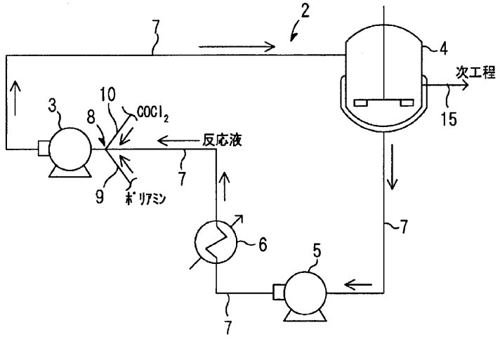
Legend: 2. Circulation section; 3. High shear pump; 4. Reactor; 5. Liquid pump; 6. Cooling device; 7. Circulation line (for reaction liquid solution); 8. Raw material mixing section; 9. Polyamine supply pipe; 10. Carbonyl chloride supply pipe; 11. Inlet end of polyamine supply pipe; 12. Polyamine supply pipe opening; 13. Inlet end of carbonyl chloride supply pipe; 14. Chlorochloride supply pipe opening; 15. Transport line to next process step (if 4 is a first stage reactor, reaction product is transported to second stage reactor).
Reaction Mechanism
The following reaction steps occur sequentially in the same reactor:
- Carbamoyl Chloride Formation: pMDA reacts with COCl₂ to form intermediate carbamoyl chloride
- Thermolysis: Carbamoyl chloride decomposes at elevated temperature to form MDI + HCl
Process Parameters
Process conditions are optimized for side reaction control to minimize urea, biuret formation:
- Temperature Range: 0-250°C (broader than aliphatic isocyanates)
- Pressure: 0-5 MPa gauge capability
- Practical Operating Temperature: Typically 100-200°C for commercial operation
- Residence Time: Several hours depending on conversion requirements
Mass Transfer Enhancement
- High-Shear Pump System: Enhanced mixing for viscous aromatic solutions
- Material-Mixing Parts: Specialized design for rapid phosgene-pMDA contact
- Circulation Technology: Closed-loop circulation maintains optimal reaction conditions
Process Control Systems
- PID Controllers: Automated control of temperature, pressure, flow parameters
- Real-Time Monitoring: Continuous monitoring of conversion and product quality
- Safety Systems: Advanced control for handling phosgene and HCl
Material Handling System
- Circulation Loop: Closed-loop system with material-mixing parts, high-shear pump, reactor, liquid-feeding pump, and cooling unit
- Mixing Technology: High-shear mixing with flow velocities 0.5-10 m/sec optimized for viscous pMDA solutions
- Flow Control: PID controllers for temperature, pressure, and flow rate management
Product Stream Management
- Monomeric MDI: 4,4'-MDI separated via distillation for elastomers/coatings
- Polymeric MDI: Oligomer mixture for rigid foam applications
- Product Flexibility: Same equipment handles both products through parameter adjustment
- Solvent Recovery: Distillation systems for solvent purification and recycle
Process Flow Diagram
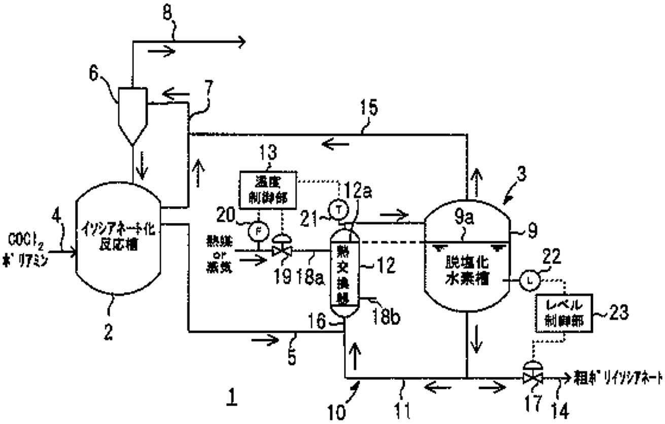
Figure 2 - Schematic configuration diagram of a polyisocyanate production facility[3]
Legend:
- Schematic configuration diagram showing an embodiment of the polyisocyanate production facility from JP2006312619A[3]
- Isocyanate reaction tank
- Dehydrochlorination process section
- Supply pipe (COCl2 and polyamine feeds)
- Supply line (reaction liquid mixture)
- Condenser
- Circulation line
- Discharge pipe (for by-produced hydrogen chloride gas and excess carbonyl chloride)
- De-hydrochlorination tank
- Thermosiphon recirculation unit
- Circulation line
- Heat exchanger
- Temperature control unit
- Extraction pipe (for crude polyisocyanate)
- Vapor line
- Mixing line
- Control valve
- Heating lines (18a aand 18b)
- Control valve
- Flow meter (for heat medium or steam)
- Thermometer
- Level meter
- Level control unit
Process Efficiency
Conversion Performance
- pMDA Conversion: >95% conversion achievable in multistage system
- MDI Yield: >90% yield based on pMDA input
- By-Product Control: <5% combined urea/biuret formation through optimized conditions
Product Quality
- Purity: >98% MDI purity after purification
- Impurity Control: <1% high-boilers, <0.5% chlorinated compounds
- Color Stability: Hazen <50 for high-quality applications
Process Integration
The MDA phosgenation is part of an integrated manufacturing complex where all major raw materials (including nitrobenzene, aniline, and phosgene), utilities, and chlorine recovery are provided by upstream plants to maximize efficiency and resource integration across the polyisocyanate value chain.
Figure 3 - Integrated Polyisocyanate production system[1]
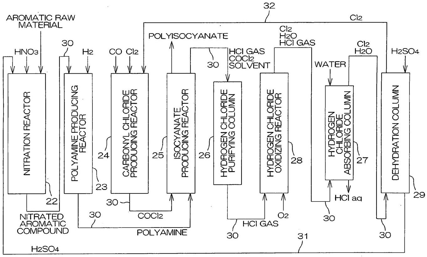
Legend: 22. Nitration reactor; 23. Polyamine producing (hydrogenation) reactor; 24. Carbonyl chloride producing reactor; 25. Polyisocyanate producing reactor; 26. Hydrogen chloride purifying column; 27. Hydrogen chloride absorbing column; 28. Hydrogen chloride oxidizing reactor; 29. Dehydration column; 30. Transfer line; 31. Sulfuric acid supply line; 32. Chlorine supply line.
References
- M. Sasaki et al. United States patent US2008154066A1: Polyisocyanate Production Method and Polyisocyanate Production System. Priority date Mar 10, 2005. Assignee: Mitsui Chemicals Polyurethanes, Inc.
- M. Sasaki et al. World patent WO2006109576A1: Apparatus for continuously producing polyisocyanate. Priority date: Mar 30, 2006. Application filed by Mitsui Chemicals Polyurethanes, Inc.
- U. Masaki et al. Japanese patent JP2006312619A: Installation and method for producing polyisocyanate.Priority date Feb 14, 2006. Application filed by Mitsui Chemicals Polyurethanes Inc.