Process Summary
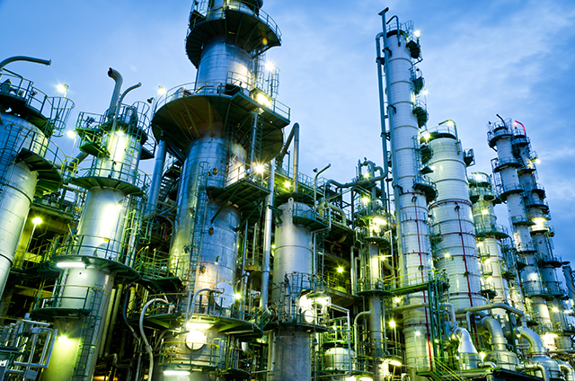
Fired heaters, or Process Heaters, are important to refineries and petrochemical plants because they heat and vaporise the hydrocarbon fluids to create necessities like gasoline, diesel, and jet fuel. Heat is produced via combustion and transferred to the crude oil or other hydrocarbon liquids by radiation, conduction, and convection. Heating and vaporizing separates oil into the products we use every day[1].
Basic Fired Heater Functions
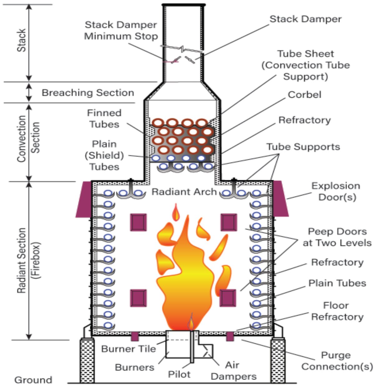
The basic functions of a fired heater are (Fig. 1) [1]:
- to produce heat ny burning fuel;
- to transfer the produced heat to the process fluid in the tubes via conduction, radiation, and convection
- to release the combustion gases created by burning fuel through a stack
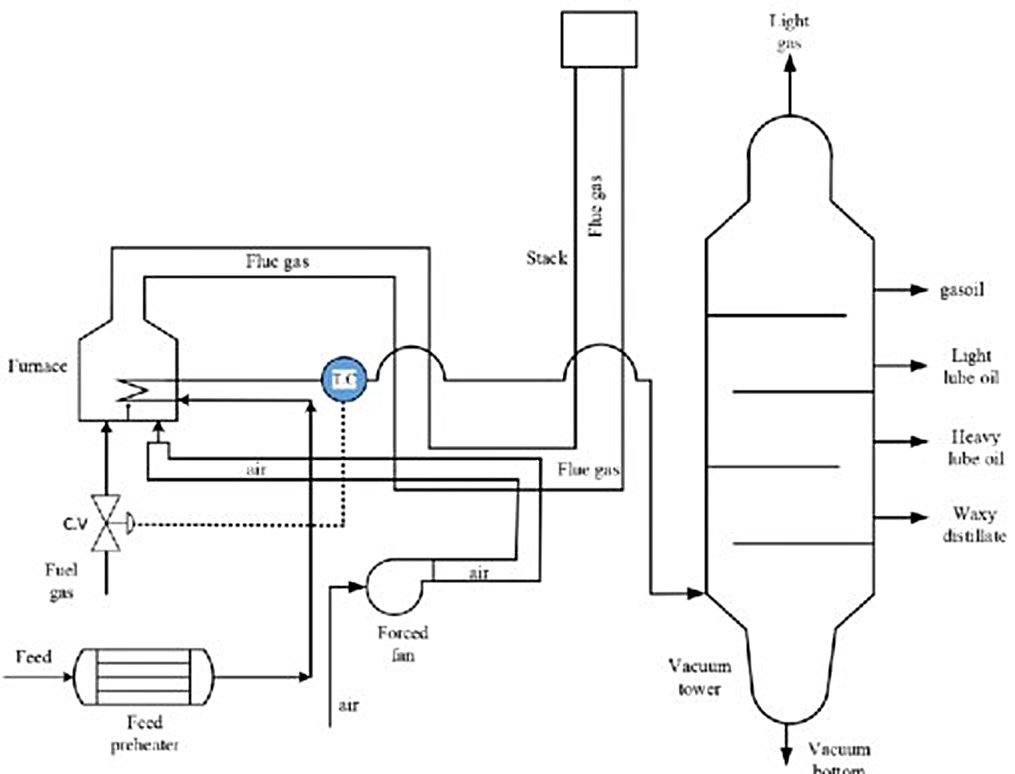
Figure 1 - Process flow diagram of furnace 200[2].
Anatomy of a fired heater
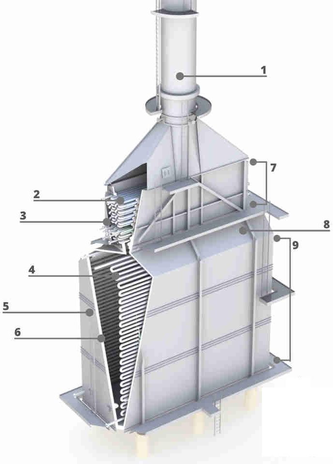
The components of a fired heater are shown in Fig. 2[1]:
Figure 2 - Anatomy of a Fired Heater.
 |
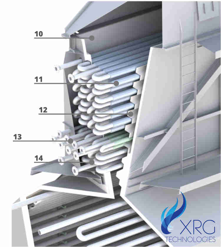 |
- Stack: exhaust chimney or vertical pipe through which flue gases escape the fired heater
- Convection Tubes: tubes located in the convection section
- Header Box: internally insulated compartment enclosing headers or manifolds
- Radiant Tubes: tubes located in the radiant section
- Casing: a metal shell, typically lined with refractory, enclosing the firebox and convection section
- Refractory Lining: heat-resistant lining; commonly made from castable or ceramic fiber
- Convection Section: area where hot flue gases leave the radiant section and circulate at high speed through a tube bundle
- Arch (or Bridgewall): location where flue gas exits the radiant section
- Radiant Section: area where tubes are directly heated by radiation from burner flames
- Breeching: transition where flue gas travels from the convection section to the stack
- Finned Tube: specialized tube with protruding fins that increase surface area and heat absorption
- Corbels: refractory material used to direct flue gases onto tubes as it passes though the convection section
- Crossover: connecting piping between any two coil sections
- Shield Section/Shock Section: non-finned tubes that shield the convection section from direct radiation
Important Terms
- Flue Gas: gas produced as a byproduct of combustion inside the fired heater
- Draft: the negative pressure of the air and/or flue gas in the heater
- Tubes/Coils: a continuous metal pipe that transports fluid through a fired heater[1]
Understanding Heat Transfer
Fired heaters utilize all three heat transfer methods: conduction, convection, radiation (Fig. 3) [1].
Figure 3 - Heat transfer types.
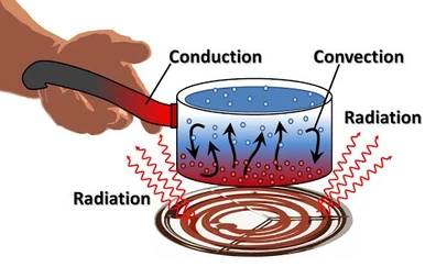
- Radiation is the transfer of energy from a heat source to objects in its path through space. In fired heaters, this occurs when heat energy is absorbed by tubes exposed to flames in the radiant section.
- Convection is the transfer of heat from one place to another via fluid movement, like gases flowing over process tubes in the convection section of the heater.
- Finally, conduction is the transfer of heat via contact between two materials or moving from one section of an object to another. In a fired heater, conduction occurs when heat transfers from the tube walls to the fluid flowing inside.
Heater Styles
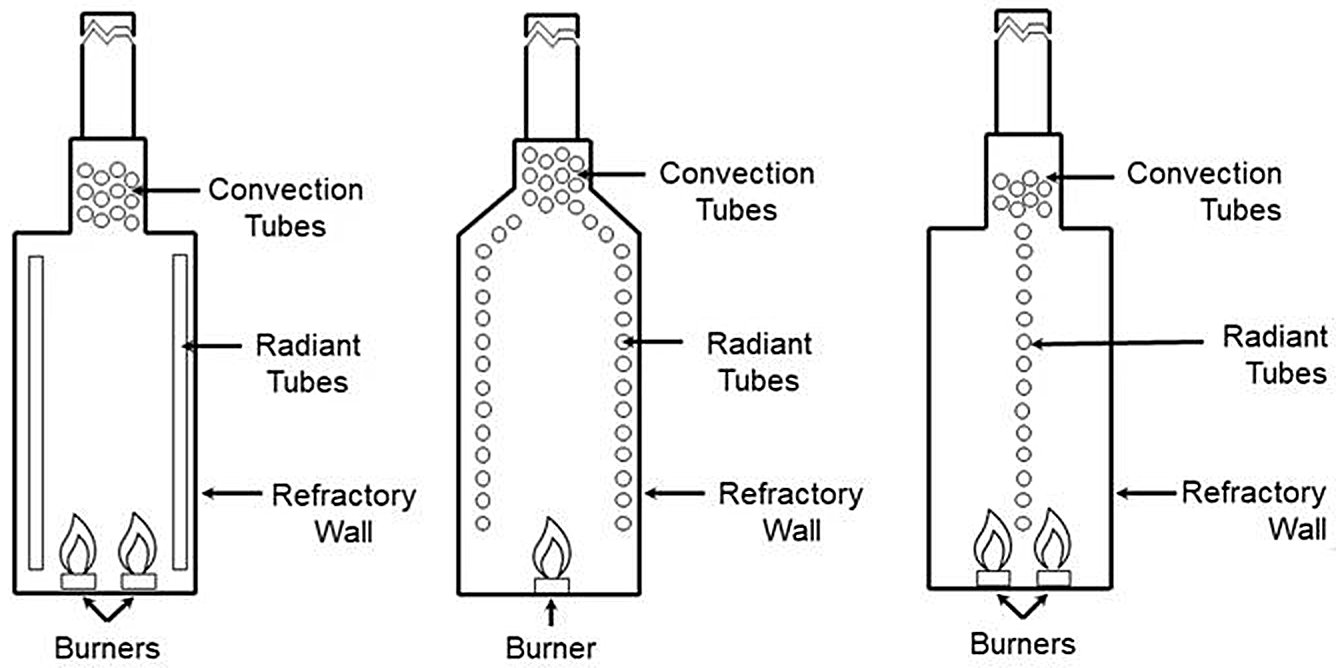
The temperature inside fired heaters can reach a toasty 2,200° F. Heater and coil combinations vary by application, but cabin/box and cylindrical style are the main types of heaters (Fig. 4). The main difference is the orientation of tubes in the radiant section. In a vertical cylindrical heater, the tubes are arranged vertically while a cabin heater’s tubes are usually horizontal[1].
Figure 4 - Different Fired Heater Styles.
|
Vertical
Cylindrical
|
Cabin
Heater |
Central tube wall
(Double Fired) |
 |
The American Petroleum Institute (API) sets the industry standards for fired heater design, with aspects ranging from material selection to burner arrangement to efficiency protocols.
Draft Systems
There are several methods to supply air and remove flue gases based on the location of draft systems relative to the heater[1].
- Natural draft: the airflow induced by negative pressure (i.e. a vacuum) in the heater relative to the pressure outside the heater. This requires no fans.
- Forced Draft (FD): air is supplied by forced draft fans that “push” air for a greater heat release per burner.
- Induced Draft (ID): fans “pull” air to remove flue gases and maintain negative pressure in the heater.
- Balanced draft: forced draft fans supply air while induced draft fans expel flue gases in a dual-fan system.
Proper Flow of Process Fluid
Properly flowing fluid is critical for optimal performance. Problems like flame impingement (flames contact tube directly) and slow flow cause heat transfer issues and equipment damage (Fig. 5) [1].
Figure 5 - Impingement in a fired heater.

Coking or fouling occurs when carbon deposits accumulate inside tubes, like plaque buildups in arteries. This buildup decreases the tube’s usable area, thus restricting flow and insulating the tube wall which leads to less heat transfer. Left uncorrected, buildup can cause tubes to rupture leading to fires and potentially dangerous situations.
References
- XRG Technologies, 29th Sep 2021, What is a Fired Heater in a Refinery? For Dummies.
- Zabihi, A. & Raazaitabari, M.R.. (2016). Decreasing emission factor of pollutants in an oil refinery by renovating the furnace design. Global Journal of Environmental Science and Management. 2.

