Process Summary
Sulfur recovery units (SRUs) are critical environmental protection systems in refineries, designed to convert hydrogen sulfide (H2S) found in natural gas or from the by-product sour gases derived from the refining of crude oil into non-hazardous elemental sulfur. These systems prevent atmospheric pollution while recovering a valuable byproduct, achieving up to 99.9% sulfur recovery efficiency in modern configurations.
SRUs primarily use the Claus process, which combines thermal and catalytic stages. Acid gas streams containing H2S are first burned in a thermal reactor at 980–1,540°C to partially oxidize H2S into sulfur dioxide (SO2). The resulting gas mixture then undergoes catalytic conversion at 200–315°C, where H2S reacts with SO2 to form elemental sulfur vapor. This vapor is condensed and collected as liquid sulfur, while remaining gases progress through multiple catalytic stages to maximize conversion.
History
In nineteenth century, there were many alkali manufacturing plants in England producing sodium carbonate (Na2CO3) by the Leblanc process. The original Claus process was developed by Carl Friedrich Claus, a chemist working in England, for the purpose of recovering sulfur from the waste calcium sulfide (CaS) generated by the Leblanc process. As a catalyst, he chose a bog iron ore and later bauxite (a mineral with a high alumina content). In 1883, Claus was granted a British patent for the process.
During the next 53 years, the Claus process underwent several minor modifications. In 1936, I.G. Farbenindustrie a (German conglomerate of chemical companies) introduced a modification of the process that utilized a thermal conversion step followed by catalytic conversion steps, which is the basically the concept currently used in modern Claus sulfur recovery units.
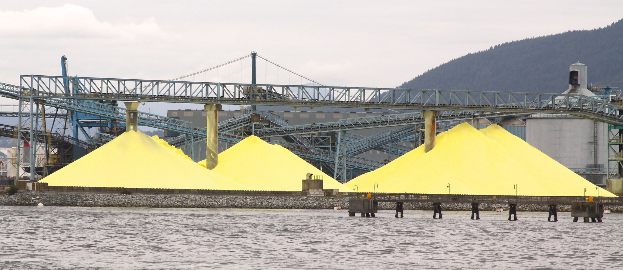
There are many hundreds of Claus sulfur recovery units in operation worldwide. In fact, the vast majority of the 80 million metric tonnes of sulfur produced worldwide in 2021 are by-product sulfur from petroleum refining and natural gas processing plants.
Figure 1 - Industrial piles of sulfur at a port
Key Chemical Reactions
The process relies on two main reactions involving hydrogen sulfide:
Thermal oxidation:
(1) H2S + 1.5 O2 → SO2 + H2O
Approximately 1/3 of H2S is converted to SO2 in this stage
Catalytic Claus reaction:
(2) 2 H2S + SO2 ↔ 3 S + 2 H2O
This equilibrium-driven reaction occurs in catalytic beds using alumina or titanium-based catalysts.
Combining equations (1) and (2), the overall process reaction is:
(3) 2 H2S + O2 → 2 S + 2 H2O
Feed Gas Composition
Claus unit feed gases have a wide range of compositions. Most of the feed gases are originate from absorption processes using various solvents to extract hydrogen sulfide from the by-product gases of petroleum refining, natural gas processing, tar sands processing, coal gasification, smelters, coke ovens and other industries. The absorption processes used for that purpose include "Amine gas treating", "Rectisol" and "Selexol" to name a few.
In addition to hydrogen sulfide extracted from by-product fuel gases by an absorption process, petroleum refineries also derive hydrogen sulfide from the steam distillation of wastewaters containing dissolved hydrogen sulfide. Those wastewaters are referred to as sour water and the steam distillation of those wastewaters is referred to as sour water stripping.
Typical composition of the Claus feed gases obtained from amine gas treating and from sour water stripping are shown in Table 1 below:
Table 1 - Typical feed gas composition for the Claus process
| From an amine process |
From a sour water stripper |
| Component |
Mol % |
Wt % |
Component |
Mol % |
Wt % |
| H2S |
82.1 |
80.8 |
H2S |
26.7 |
40.2 |
| CO2 |
11.9 |
15.1 |
CO2 |
2.6 |
5.1 |
| NH3 |
nil |
nil |
NH3 |
39.4 |
29.7 |
| H2O |
4.0 |
2.1 |
H2O |
31.3 |
25.0 |
| HC* |
2.0 |
2.0 |
HC |
nil |
nil |
*Hydrocarbons
The amount of hydrogen sulfide derived from sour water stripping in a petroleum refinery is much lower than is derived from the refinery's amine gas treating of by-product fuel gases.
Gases with an H2S content of over 25% are suitable for the recovery of sulfur in straight-through Claus process units (as described in the next section). Other process design configurations can be used to handle gases with lesser amounts of H2S.
Process Flow
A typical SRU follows the sequence shown in Fig. 2:
Figure 2 - Schematic Diagram of a Claus sulfur recovery plant
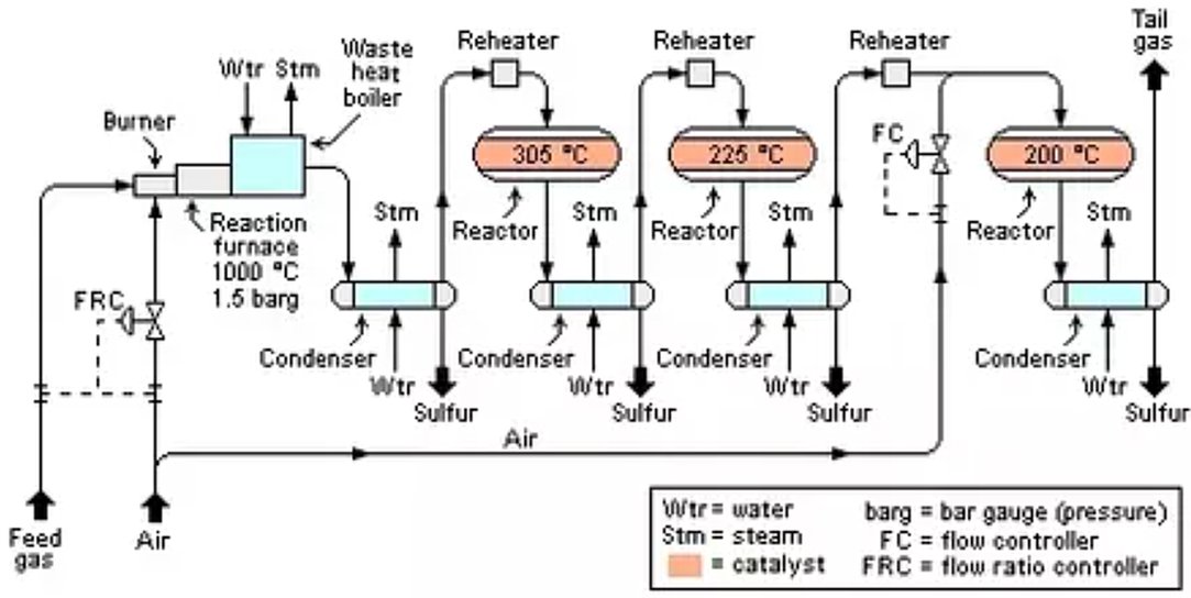
- Thermal Reactor: Burns acid gas with air/O2, generating SO2 and recovering ~70% sulfur via direct combustion. The reaction furnace pressure and temperature are maintained respectively at about 1.5 bar gauge (barg) and about 1,000 °C.
- Waste Heat Boiler: Cools gases from 1,200°C to 350°C, recovering heat as medium-pressure steam. The gas is then further cooled and condensed in a heat exchanger while producing additional steam. The condensed liquid sulfur is separated from the remaining unreacted gas in the outlet end of the condenser and sent to product storage.
- Catalytic Reactors: Two to three stages convert remaining H2S/SO2 mixtures. Gas is reheated before each reactor to maintain reaction kinetics. Outlet product gas from each reactor is cooled in another condenser while also producing steam
- First catalytic reactor: maintained at an average temperature of about 305 °C. About 20% of the H2S in the feed gas is thermally converted into elemental sulfur.
- Second Catalytic Reactor: maintained at an average temperature of about 225 °C. About 5% of the H2S in the feed gas is thermally converted into elemental sulfur.
- Third Catalytic Reactor: maintained at an average temperature of about 200 °C. About 3% of the H2S in the feed gas is thermally converted into elemental sulfur.
- Sulfur Condensers: after each stage, separate liquid sulfur from the remaining unreacted gas in the outlet end of the condenser, storing it in molten pits for shipment.
Efficiency and Byproducts
For a well-designed and operated Claus sulfur recovery plant having three catalytic reactors (as shown in the flow diagram), an overall conversion of at least 98% can be achieved. In fact, the latest modern designs can achieve up to 99.8% conversion of hydrogen sulfide into product sulfur that is 99+% saleable "bright yellow sulfur".
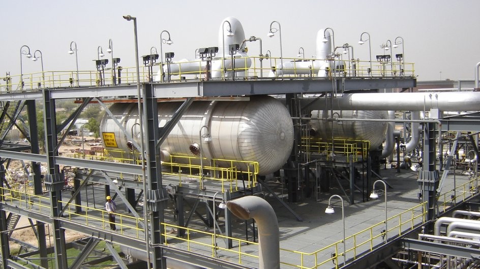
Figure 3 - Sulfur Recovery Installation
The remaining gas separated from the last condenser is referred to as "tail gas" and is either burned in an incinerator or further desulfurized in a "tail gas treatment unit".
- Sulfur yield: 95-98+% from Claus stages alone; 99.9% with tail gas units.
- Energy: Waste heat boilers generate 600–800 kPa steam, offsetting 80% of unit energy needs.
- Emissions: Final exhaust contains <150 mg/Nm³ SOx, meeting World Bank standards.
- Waste streams: Treated tail gas (N2, CO2, H2O) and minor ammonium nitrate deposits from NH3 combustion.
Catalysts
The catalytic reactors each contain a bed of catalyst with a depth of about 90 to 120 cm. The most widely used Claus reaction catalyst is porous aluminum oxide (Al2O3), commonly referred to as alumina. The alumina catalyst owes its activity to a very high surface area of 300 m²/g or higher. About 95 % of that surface area is provided by pores having diameters of less than 8 nm (80 angstroms).
The catalyst not only increases the kinetics (i.e., the rate of reaction) of the Claus reaction equation (2), but it also hydrolyzes the carbonyl sulfide (COS) and carbon disulfide (CS2) that is formed in the reaction furnace:
(4) COS + H2O → H2S + CO2
(5) CS2 + 2 H2O → 2 H2S + CO2
The H2S formed as per the hydrolysis equations (4) and (5) is then converted into elemental sulfur as per the Claus reaction (1). Most of the hydrolysis occurs in the first Claus reactor.
Other Claus catalysts based on titanium dioxide (TiO2) are also used. The titanium dioxide catalysts are produced from anatase, one of the three naturally occurring mineral forms of titanium dioxide. They are also called titania catalysts and are said to be more resistant to thermal aging than the alumina catalysts. They are also said to have a higher activity for the hydrolysis of COS and CS2 which allows the first Claus reactor to operate at lower temperatures compared to alumina catalysts. However, they are significantly more expensive than the alumina catalysts.
References
- CAMEL Climate Change Education, 29th April 2016, Claus Process.
- U.S. Environmental Protection Agency (EPA), AP-42, CH 8.13: Sulfur Recovery, Modified: 25th Oct 2005.
- National Energy Technology Laboratory (NETL), The Claus Process.
- Wikipedia, Claus Process.
- F. Manenti et al., 8th Feb 2014, Model-based optimization of sulfur recovery units, Politecnico di Milano.
- F. Pourfayaz et al., Simultaneous Optimization of Sulfur Recovery Efficiency and Thermal Energy Generation in the Catalytic Section of the Sulfur Recovery Unit Simulated Based on Reaction Kinetics. ACS Omega. 2025 May 21;10(21):21262-21279. doi: 10.1021/acsomega.4c10709. PMID: 40488082; PMCID: PMC12138708.
- J.A. Lagas et al., 1988, The SUPERCLAUS Process. Proceedings of the Laurance Reid Gas Conditioning Conference.
- Mohamed Ibrahim Seddik, 14th Oct 2017, The Importance of Analyzers to Monitor the Performance of the Sulfur Unit, LinkedIn article.
- U.S. Geological Survey, 2022, Mineral Commodity Summaries: Sulfur.
- World Bank Group, 2020, Environmental, Health, and Safety Guidelines for Petroleum Refining.
- National Energy Technology Laboratory (NETL), 6.2.2. Sulfur Recovery and Tail Gas Treating.
- National Energy Technology Laboratory (NETL), SCOT Tail Gas Treating.