A liquid fuel-fired power plant converts chemical energy from liquid fuels (like fuel oil or diesel fuel) into electrical power through thermal processes. Oil-fired power plants can use different types of liquid fuels, but there are important distinctions in how these fuels are typically used:
Plant Types
Steam Cycle/Combined Cycle Power Plants
- Can burn both heavy fuel oil (HFO) and diesel
- HFO is preferred due to lower cost, despite requiring additional processing equipment
- Diesel is sometimes used as a backup or startup fuel
Diesel Engine Power Plants
- Primarily use diesel fuel or HFO in large reciprocating engines
- Large four-stroke diesel engines (5-20MW) typically run on HFO with 40-45% efficiency
- Small diesel generators (<1MW) typically use diesel fuel due to simpler handling requirements
Steam/Combined Cycle Oil-fired Power Plant
A liquid fuel-fired power plant converts chemical energy from liquid fuels (like fuel oil or diesel) into electrical power through thermal processes. Oil-fired power plants primarily serve as backup power generation and are common in oil-rich regions, offering advantages like quick startup capability, reliable fuel storage, and flexible operation, though they are less efficient and more costly to operate than natural gas plants.
Core Components
- Fuel system
- Storage tanks for raw and processed fuel
- Fuel treatment systems for cleaning and heating
- Fuel pumps and control valves
- Filtration equipment for particulate removal
- Steam Generation
- Boiler with specialized liquid fuel burners
- Water walls for steam generation
- Superheater and reheater sections
- Economizer for feedwater heating
- Air and Gas Systems
- Forced draft fans for combustion air
- Induced draft fans for flue gas extraction
- Air preheaters
- Stack for exhaust gases
Plant Configurations
- Steam Cycle Plants
- Traditional configuration using boiler and steam turbine
- Efficiency ranges from 36-40%
- Suitable for base load operation
- Combined Cycle Plants
- Integrates gas turbines with steam generation
- Uses waste heat recovery steam generators
- Achieves higher efficiency up to 55-60%
- Greater operational flexibility
Dual-fuel Capability
Modern oil-fired power plants are often designed with dual-fuel capability, allowing them to switch between different liquid fuels depending on availability and economic considerations, though they typically don't burn multiple fuels simultaneously
|

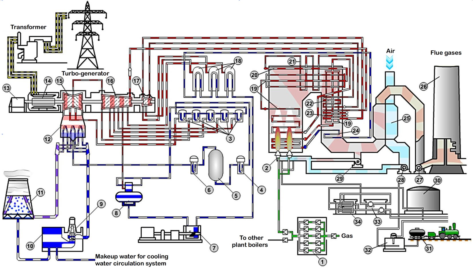
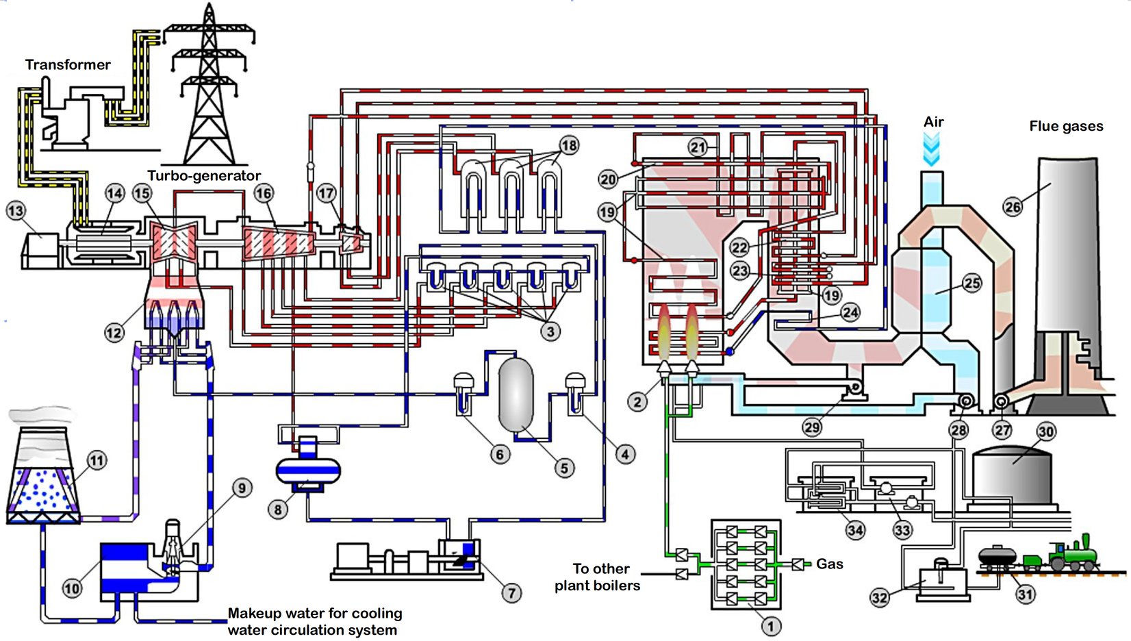
Gas/Fuel Oil Power Plant Technical Scheme.
Credit: Prof. P.A. Shchinnikov, Assoc. Prof. I.V. Borodikhin, Novosibirsk State Technical University
1. Gas Reduction Station; 2. Gas-fuel oil burners; 3. Low Pressure Heater;
4,5,6. Water Treatment Equipment; 7. Feed Water Pump; 8. Deaerator;
9,10. Circulation Pump; 11. Cooling Tower; 12. Condenser; 13. Exciter;
14. Generator; 15. Low Pressure Turbine; 16. Medium Pressure Turbine;
17. High Pressure Turbine; 18. High Pressure Heater; 17. Evaporative Surfaces;
20. Ceiling Superheater; 21.Convective Superheater 1st Stage; 22. Convective Superheater 2nd Stage; 23. Secondary Superheater; 24. Economizer;
25. Regenerative Air Preheater; 26. Chimney; 27. Induced Draft Fan; 28.Forced Draft Fan; 29. Pressure Reducing Device; 30. Fuel Oil Tank; 31. Drain Device;
32. Reception Tank; 33. Pumps; 34. Filters
|
Diesel-Engine Based Power Plant
The main advantage of diesel engine plants is their high efficiency in smaller sizes and operational flexibility, though they typically have higher fuel costs compared to other types of power plants.
Core Components
- Engine System
- Multiple diesel engines (typically 4-stroke)
- Direct coupling to electrical generators
- Fuel injection systems
- Engine cooling systems
- Lubrication systems
- Fuel System
- Day tanks for immediate supply
- Main storage tanks
- Fuel treatment systems (filtration, heating if using heavy fuel oil)
- Fuel transfer pumps
- Fuel purification equipment
- Auxiliary Systems
- Starting air system
- Cooling water circuits
- Exhaust gas system
- Ventilation system
- Sound attenuation equipment
Operational Characteristics
- Performance Features
- Quick start capability (minutes)
- High thermal efficiency (40-45%)
- Good part-load efficiency
- Multiple engine units for reliability
- Applications
- Standby power generation
- Remote locations
- Island power systems
- Peak load operation
- Industrial facilities
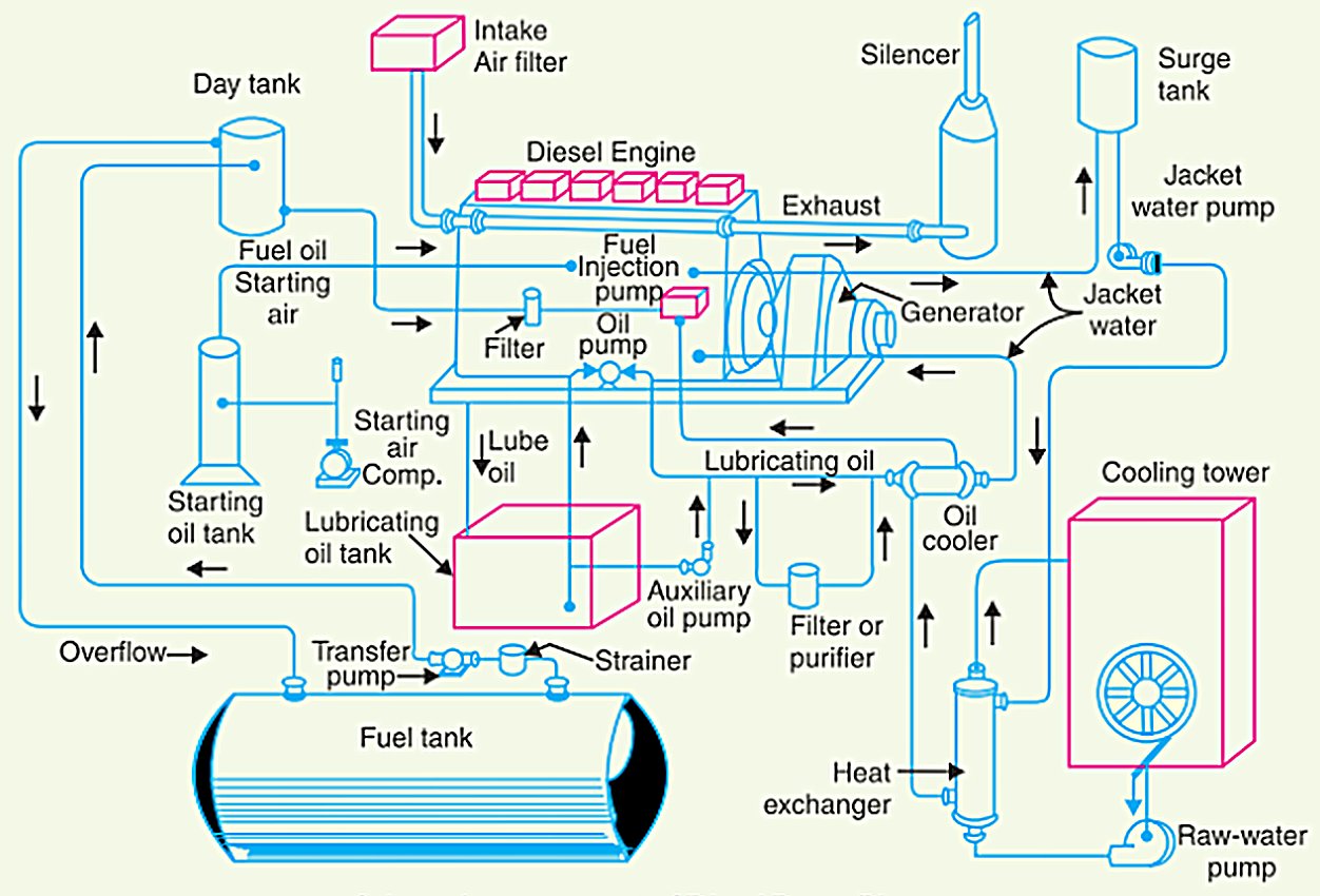
Diesel-Engine Powr Plant Layout
|

Schematic arrangement of a diesel engine power plant
Credit: Electrical Live.
|
Environmental Systems
Like other fuel-fired power plants, oil-fired and diesel power plants may be equipped with emissions control measures and devices, such as:
- NOx reduction systems
- Particulate removal equipment
- Flue gas treatment systems
- Waste heat management


