Process Flow Summary
- Multi-stage flash only: in the multi-stage flash variant, all four stages are used and no distillation column follows. A direct-fired or hot oil feed heater upstream of the final flash vessel raises condensate temperature to 120–160°C to ensure adequate stripping to meet the RVP specification.
- Distillation column only: in the pure distillation variant, the flash stage is omitted entirely and raw condensate from the slug catcher proceeds directly to feed preheating and the stabiliser column.
- Combined flash + distillation column: in the combined variant, only the 1st Flash (HP) stage is used to remove bulk C₁–C₂ (flash gas), after which the pre-flashed condensate proceeds to the stabiliser column. This reduces column diameter and reboiler duty by 20–35% compared to the pure distillation variant.
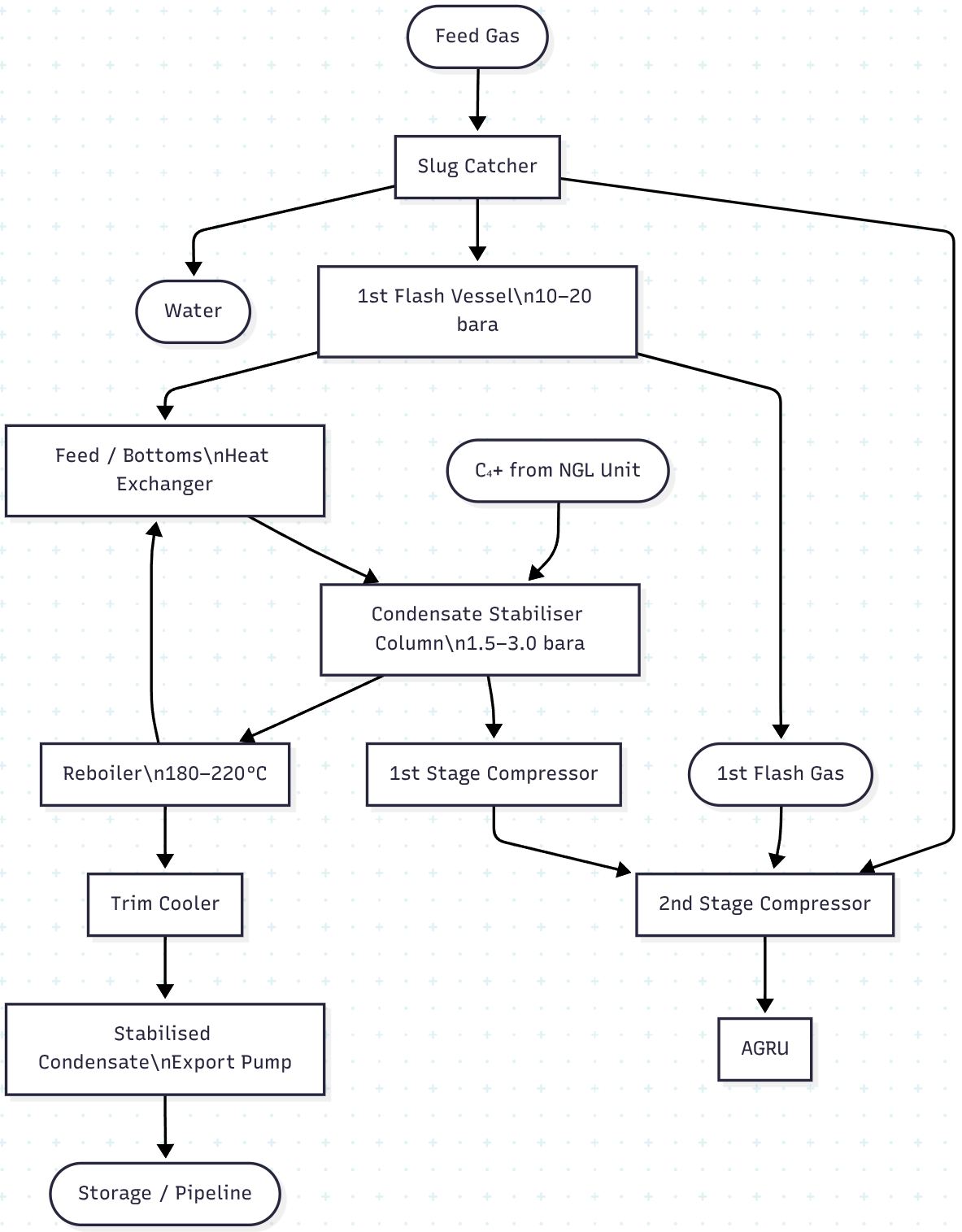
Figure 1 — Condensate stabilisation simplified block flow diagram encompassing all three options (multistage flash only, distillation column only, combined flash + distillation column
Diagram code is shown in the appendix.
Process Flow Description
Step 1 — Feed Gas Inlet & Slug Catcher
Raw feed gas from the gathering system or wellheads enters the slug catcher at high pressure (typically 30–80 bara). The slug catcher performs the first three-phase separation:
- Gas phase — exits the top of the slug catcher and is routed forward to the 2nd Stage Compressor suction header and subsequently to the AGRU
- Liquid condensate — exits the bottom and is routed via a level control valve to the MP Flash Drum
- Produced water — separated and removed at the base of the slug catcher for routing to produced water treatment
Step 2 — Flash Pre-treatment
(Multi-stage flash and combined variants only — omitted in pure distillation column variant)
Raw condensate undergoes one or more flash stages at progressively decreasing pressures to remove dissolved light ends before entering the stabiliser column or proceeding directly to final stabilisation:
| Flash Stage |
Pressure (bara) |
Flash Gas Composition |
Gas Destination |
| 1st Flash (HP) |
10–20 |
C₁–C₂ rich |
Overhead compressor directly |
| 2nd Flash (MP) |
3–6 |
C₁–C₃ |
Intermediate compressor stage |
| 3rd Flash (LP) |
1.5–2.5 |
C₂–C₄ |
1st Stage Compressor |
| Final Flash |
~1.1 |
C₃–C₄ rich |
1st Stage Compressor |
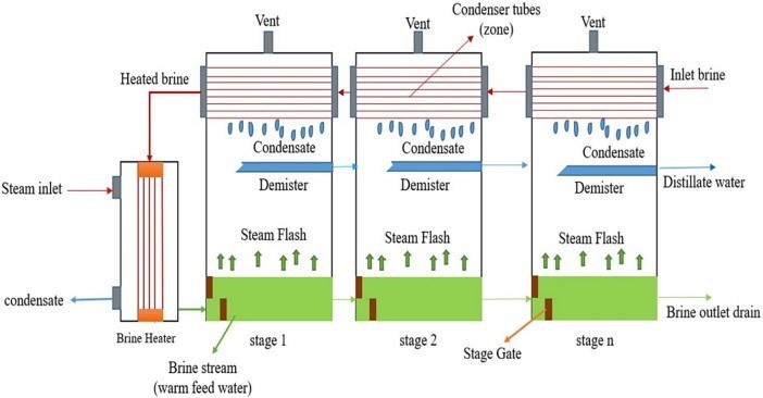
Figure 2 — Simplified diagram of a typical multistage flash vaporization unit
Step 3 — Feed Preheating
(Distillation column and combined variants only)
Pre-flashed condensate (or raw condensate in the pure distillation variant) is preheated in a feed/bottoms shell & tube heat exchanger against the hot stabilised condensate bottoms product, recovering reboiler heat and reducing overall energy consumption. Feed temperature at column inlet is typically 120–160°C.
Step 4 — Condensate Stabiliser Column
(Distillation column and combined variants only — omitted in pure multi-stage flash variant)
Preheated condensate enters the stabiliser column at mid-point. The column operates as a distillation unit with a bottom reboiler providing the stripping vapour that drives light ends upward and out of the column overhead:
| Parameter |
Typical Value |
| Column operating pressure |
1.5–3.0 bara |
| Column top temperature |
50–80°C |
| Column bottom temperature |
180–220°C |
| Number of trays |
15–25 (or equivalent packing height) |
| Reflux ratio |
0 (simple stabiliser) to 0.3–1.0 (with condenser) |
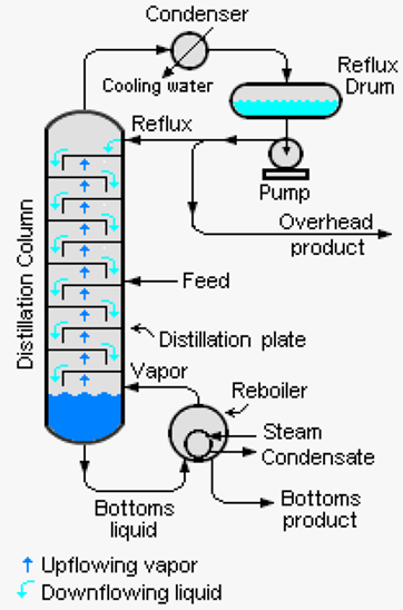
Figure 3 — Simplified diagram of a typical condensate distillation column [5]
A C₄⁺ recycle stream from the associated NGL unit may be introduced into the column feed to maximise liquid hydrocarbon recovery and provide additional stripping vapour.
- Column overhead vapour (stabiliser overhead gas, C₁–C₄ rich) → 1st Stage Compressor
- Stabilised condensate → reboiler → feed/bottoms heat exchanger → trim cooler → export
An optional overhead condenser and reflux drum may be installed where an LPG-quality overhead product is desired; in simple stabiliser designs, the overhead vapour is left uncondensed and routed directly to compression.
Step 5 — Reboiler
(Distillation column and combined variants only)
The reboiler (direct-fired heater or kettle/thermosyphon hot oil exchanger) maintains the column bottom temperature at 180–220°C, generating the stripping vapour required to meet the target RVP specification. In the combined variant, reboiler duty is reduced by 20–35% due to the upstream pre-flash step.
Step 6 — Flash Gas & Overhead Gas Compression
(All variants)
All liberated vapour streams are recompressed in a two-stage compression system before routing to the AGRU:
- 1st Stage Compressor — handles low-pressure streams: stabiliser overhead gas (column variants) and/or LP/final flash gas (flash variants); recompresses to intermediate pressure
- 2nd Stage Compressor — handles combined streams from slug catcher overhead, HP flash gas, and 1st Stage Compressor discharge; recompresses to AGRU inlet pressure
In the multi-stage flash variant, the number of compressor stages matches the number of flash pressure tiers.
Step 7 — Stabilised Condensate Cooling & Export
(All variants)
Hot stabilised condensate (180–220°C from column bottom, or 40–80°C from final flash vessel) is cooled through:
- Feed/bottoms heat exchanger (column variants) — recovering heat into the column feed
- Trim cooler (air-cooled or water-cooled) — reducing product temperature to 40–60°C
The cooled stabilised condensate is pumped to atmospheric storage tanks or the export pipeline.
Product specification: RVP 8–12 psi (0.55–0.83 bara) at 37.8°C.
C₅⁺ recovery: >90% (flash only), >95% (distillation only), >97% (combined).
Equipment & Devices — Complete List
| Equipment / Device |
Variants |
Type / Notes |
| Equipment / Device |
Variants |
Type / Notes |
| Slug Catcher |
All |
Finger-type or vessel-type; 3-phase (gas / condensate / water) |
| Flash Vessel(s) |
A, C |
Horizontal 2-phase separator; one per flash pressure stage |
| Water Knockout Drum |
All |
3-phase; on stabiliser feed circuit or slug catcher outlet |
| Stabiliser Feed Heater |
A |
Direct-fired heater or hot oil exchanger; upstream of final flash |
| Feed/Bottoms Heat Exchanger |
B, C |
Shell & tube; condensate/condensate service |
| Condensate Stabiliser Column |
B, C |
Trayed (15–25 trays) or structured packing |
| Overhead Condenser |
B, C (optional) |
Air-cooled or water-cooled; only where reflux or LPG recovery required |
| Reflux Drum |
B, C (optional) |
Horizontal vessel; pairs with overhead condenser |
| Reboiler |
B, C |
Direct-fired heater or kettle/thermosyphon hot oil type |
| Hot Oil Heater / Circulation System |
B, C |
Where indirect reboiler heating is used |
| Stabilised Condensate Trim Cooler |
All |
Air-cooled or water-cooled exchanger |
| 1st Stage Compressor |
All |
Reciprocating or centrifugal; LP flash gas or stabiliser overhead |
| 2nd Stage Compressor |
All |
Centrifugal; combined gas streams to AGRU pressure |
| Compressor Interstage Coolers |
All |
Air-cooled; one per compression stage |
| Compressor Interstage Knockout Drums |
All |
Horizontal; liquid removal between compression stages |
| Reflux Pump |
B, C (optional) |
Centrifugal; where overhead condenser and reflux drum installed |
| Stabilised Condensate Export Pump |
All |
Centrifugal; product transfer to storage or export pipeline |
| Hot Oil Circulation Pump |
B, C |
Where hot oil reboiler circuit is used |
| Level Control Valves (LCV) |
All |
On slug catcher, flash vessels, column sump, reflux drum |
| Pressure Control Valves (PCV) |
All |
On flash vessel overheads and column overhead |
| Temperature Controllers |
All |
On reboiler outlet, feed heater, trim cooler outlet |
| Pressure Safety Valves (PSV) |
All |
On all pressure vessels |
| Anti-surge Controllers |
All |
On centrifugal compressors |
| Feed Inlet Strainer / Coalescer |
All |
Protects downstream equipment from solids and free water |
| Chemical Injection Points |
All |
Corrosion inhibitor, demulsifier |
| Flare Connections |
All |
Emergency depressurisation on all pressure vessels |
Appendix — plain text / ASCII art diagram code
flowchart TD
A([Feed Gas]) --> B[Slug Catcher]
B --> C([Water → Produced Water Treatment])
B --> D([Gas → 2nd Stage Compressor → AGRU])
B --> E[1st Flash Vessel\n10–20 bara]
E --> F([1st Flash Gas → 2nd Stage Compressor])
E --> G[Feed / Bottoms\nHeat Exchanger]
H([C₄+ from NGL Unit]) --> I
G --> I[Condensate Stabiliser Column\n1.5–3.0 bara]
I --> J([Overhead Gas → 1st Stage Compressor\n→ 2nd Stage Compressor → AGRU])
I --> K[Reboiler\n180–220°C]
K --> G
K --> L[Trim Cooler]
L --> M[Stabilised Condensate\nExport Pump]
M --> N([Storage / Pipeline])
Back to diagram